The Compute Edge Attributes tool computes orientation and street adjacency attributes for each edge of a shape. The computed edge attributes can then be used from CGA to drive model generation that is based on individual edge attributes.
Use the tool
Select the shapes
- Select the shapes you want to apply the tool.
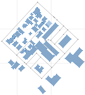
Selected shapes The tool will compute the edge attributes for every selected shape with respect to the visible street segments, i.e. it is not necessary to select the street segments.
Note:
The algorithm currently only works for static shapes (see shapes). If you want to calculate edge attributes for dynamic shapes, you first need to convert them to static shapes using Graph > Convert to Static Shapes.
- Click Shapes > Compute Edge Attributes.
This opens the tool dialog which provides numerous parameters to configure the algorithm. The algorithm and the parameters are explained in detail below. For the general use case, it is okay to use the default parameters and just press Apply to execute the algorithm.
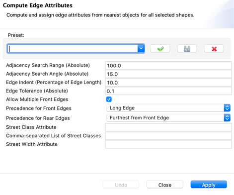
Compute Edge Attributes dialog box
Inspect the computed edge attributes
After the tool is run, each selected shape is assigned the computed edge attributes. The following images illustrate how the shape attributes (in this case from an OSM data source) for a selected shape are enhanced with edge attributes after running the tool.
The selected shape to compute the attributes for:
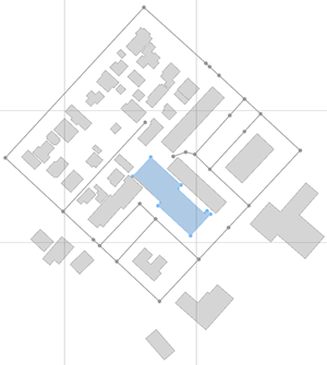
Shape attributes before running the tool:
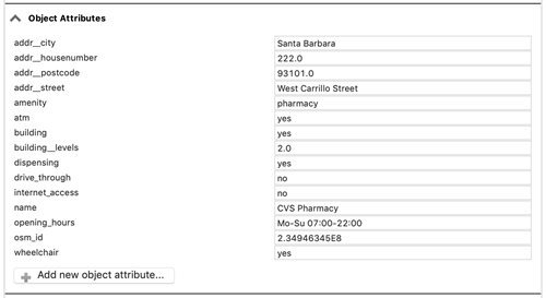
Shape attributes after running the tool:
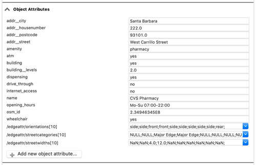
As shown, the tool adds three shape attributes which contain a list of values for each edge, starting with the edge at index 0:
- /edgeattr/orientations: The orientation of an edge.
- Front: Assigned to edges oriented to the front, typically the main road.
- Rear: Assigned to edges on the opposite of front edges.
- Side: Assigned to edges between Front and Rear
- Inner: Assigned to edges that are part of a shape’s hole.
- /edgeattr/streetcategories
- <category>: Assigned to the edge if it is facing a street.
- NONE: Assigned to the edge if it is not facing a street.
- /edgeattr/streetwidths
- <width>: Assigned to the edge if it is facing a street.
- NaN: Assigned to the edge if it is not facing a street.
Use computed edge attributes from CGA
The computed edge attributes can be accessed from CGA using the edge attribute functions.
Description of algorithm and parameters
The algorithm to calculate the edge attributes runs in three phases: Phase 1 computes the adjacency information; Phase 2 determines the edge orientation; and Phase 3 creates the shape’s edge attributes.
Computation of adjacency information
Computation of adjacency information is based on an algorithm that looks for the closest street edges from the current shape edge within a given range. The range is controlled by a number of parameters, as illustrated in the following image:
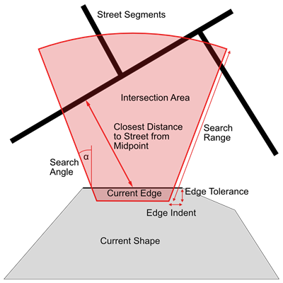
- Adjacency Search Range: Absolute range to search for adjacent shapes and street segments (default value: 100.0).
- Adjacency Search Angle: Absolute angle to search for adjacent shapes and street segments (default value: 15.0).
- Edge Indent: Relative indent from both corners of an edge, in percentage of edge length (default value: 10.0).
- Edge Tolerance: Absolute offset towards inside of a shape for increased tolerance to correctly handle overlapping shapes (default value: 0.1).
Computation of edge orientation
First, the front edge (or the front edges if Allow Multiple Front Edges is selected) is determined:
- The algorithm iterates over all edges and selects those facing a street.
- Of those facing a street, the one(s) with the lowest street class is/are selected.
- If only one front edge is allowed, and multiple edges are facing the streets of the same class, the longest or the shortest edge is selected, depending on the precedence setting for front edges (Precedence for Front Edges).
- Once the front edges are determined, the algorithm computes the rear edges. Depending on the precedence setting for rear edges, either the ones that are furthest from front edges or the ones that are most parallel to front edges are chosen (Precedence for Rear Edges).
- The remaining edges are assigned as side edges (or inner edges in case they are part of a hole in a shape).
Creation of edge attributes
As indicated above, the algorithm depends on adjacent streets’ category and width attributes. It is possible to configure which street attributes are taken using the following algorithm parameters:
- Street Class Attribute: The name of the attribute to be used to obtain the street class from a street edge. If left empty, the built-in Major / Minor attribute is used.
- Comma-separated List of Street Classes: This allows the user to define an ordered list of street categories which are used for sorting and determine the front edges. For example, assume that your street network contains an attribute “street_class” with values “freeway”, “highway”, “backroad”. Then you would set the street class attribute to “category” and the street class list to “freeway, highway, backroad” to make sure the precedence is properly used.
- Street Width Attribute: The name of the attribute to be used to obtain the street width from a street edge. If left empty, the built-in street width is used.