To take advantage of the push/pull tools in CityEngine do the following:
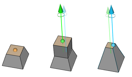
- Select a shape drawing tool (polygon, rectangle or circle tool) and hover over a shape.
- Click the orange handle to extrude the shape.
Extrude face
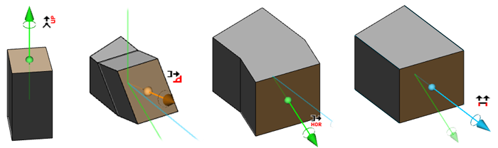
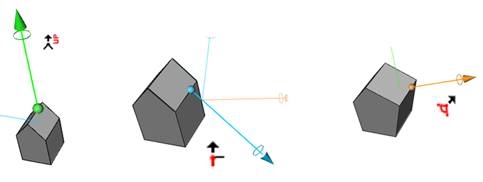
Depending on the shape, multiple arrows can appear. This allows you to create shapes along different directions. Simply hover the mouse over the desired direction arrow for immediate feedback. There are 4 different types of directions:
- Global y axis (up)
- Face normal
- Face normal projected on the ground plane
- Special directions from adjacent faces
Note:
Any shape tool can be selected when you hover over a shape to display extrusion handles. All shape creation tools support automatic splitting, snapping, and 3D editing. You can temporarily deactivate snapping when drawing by pressing Shift.
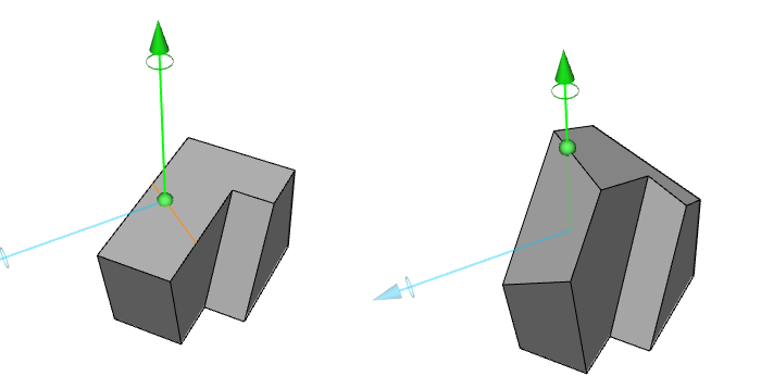
All directions have a unique color and mouse icons, as shown here:
In the 4th case, all edges are extended along their adjacent face while dragging. When the 4th case has the same direction as another arrow, the arrow is displayed with a slight offset. Here is an example of the difference between up and special edge direction dragging:
Force edge creation
To force the creation of new edges when starting a 3D drag operation, press the CTRL key.
Draw on handle
If you want to create a line on a position obscured by a handle, hover the mouse for three seconds over the handle. This causes the handle to disappear, allowing you to draw on this position.
3D shape editing
All the previously introduced polygonal operations can also be performed on 3D shapes: Snapping, splitting and automatic closing. Split parts can be moved to further refine the 3D model. Here is an example consisting of a split, 3D move, another split and move is shown:
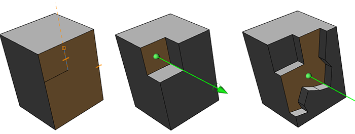
3D edge move
Select the any of the shape creation tools, and hover over existing edges. This shows an orange handle, allowing edge movements. As with the face dragging, after a click and drag, multiple directions can be shown. These include:
- Global y axis (up)
- Along adjacent faces
- Along average face normal
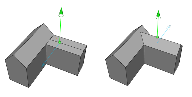
Here is an example:
While moving edges, connected faces are intelligently updated to maintain planarity. Furthermore, the moved edge is intersected with neighboring polygons. Both features are very useful for creating roofs, as shown here: