To access the tutorials in CityEngine, click Help > Download Tutorials and Examples.... After choosing a tutorial or example, the project is automatically downloaded and added to your workspace.
Create a terrain
Typically, the starting point of a CityEngine scene is the creation of a terrain. Terrains can be created from simple image files or from Digital Elevation Models (DEMs). In the latter case—for example, with a GEOTif file—the georeferencing information is supported.
Currently, CityEngine only supports image-based terrains (gray scale height maps); it does not support 3D meshes. If you only have a 3D mesh, or any other data type, you need to convert it to a heightmap using a tool such as Leveller by Daylong Graphics (http://www.daylongraphics.com/).
- Open the Part_1_Start.cej file.
- Open the maps folder, and drag and drop the elevation.jpg image into the viewport.
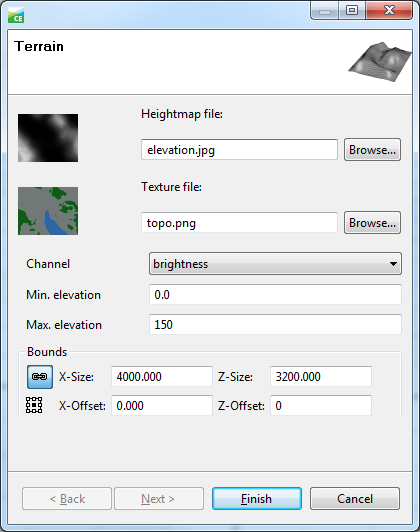
The Terrain Import dialog box appears.
- Change the Texture file to the topo.png file using the Browse button.
- Edit the bounds so the dialog box looks like the following screen shot.
If you load an image without geolocation information, its pixel resolution is set as the terrain dimensions.
Notice the Keep ratio and Alignment buttons (default value is centered; edit by clicking the icon).
- Edit the min and max elevation values (= black and white pixel value elevations), and click Finish.
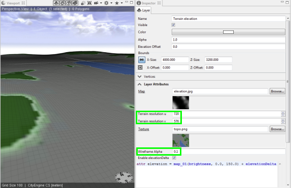
Once the terrain map layer is created, you can select it in the Scene Editor and see its attributes in the Inspector window.
Note:
You can edit the Terrain Resolution (the number of subdivisions of the terrain plane) and the Wireframe Alpha values. The latter shows the wireframe lines on the terrain, if, in the viewport’s display options, the Wireframe on Shaded/Textured option is activated (toggle with 7).
- Explore the terrain’s attributes.
Grow streets–Heightmap and Obstaclemap
Grow streets–Alignment to the terrain
In Tutorial 1, you learned how to grow streets on a flat grid with no elevation present. You'll now use the Grow Streets algorithm to directly adapt the grown streets to the actual terrain elevation.
- Click Graph > Grow Street to open Grow Streets dialog box and expand Environment Settings.
- Change the Heightmap drop-down option to your terrain’s name.
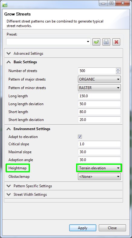
- Grow some streets, and see how they automatically align to the terrain.
Grow streets–Obstaclemap
You may have noticed that the Grow Streets functionality grows streets randomly. This includes areas where you may want to have no streets at all. To allow you to leave those areas empty and minimize the manual cleanup process, CityEngine has an ObstacleMap feature. An obstacle map is a black and white image, where the brightness defines the growable regions. To create an obstacle map, complete the following steps:
- Right-click your streets in the Scene Editor and choose Delete to remove your previously generated streets.
- Click Layer > New Map Layer > Obstacle.
- Browse to the obstacles.png image file provided in the tutorial maps folder.
- Define the same extent as your terrain’s extent.
- Leave the channel on brightness.
- The Obstacle Threshold defines the image brightness, which distinguishes between obstacle and non obstacle.
Once the Obstacle layer is created, select it and check its Layer Attributes tab in the Inspector. You'll find the following code, which determines the attribute mapping, in this case as a Boolean value (true/false):
attr obstacle = brightness < 0.5
- Hide the Obstacle Layer in the Scene Editor so it does not interfere visually with the terrain.
- Open the Grow Streets dialog box again and assign the obstacle map.
- Grow again.
- To grow more streets in specific regions, select some existing graph segments before growing more streets.
Streets–Cleanup Graph tool
Under certain circumstances, CityEngine’s Dynamic City Layouts system may not be able to solve a conflicting part of the street network as proper shapes. In that case, CityEngine highlights the conflicting graph segments in red.
To solve this, you can manually fix the issues by editing street widths, curve radii, or other parameters, but this can be tedious work. A shortcut is to use the Cleanup Graph tool.
- Find a conflicting graph segment (or create one).
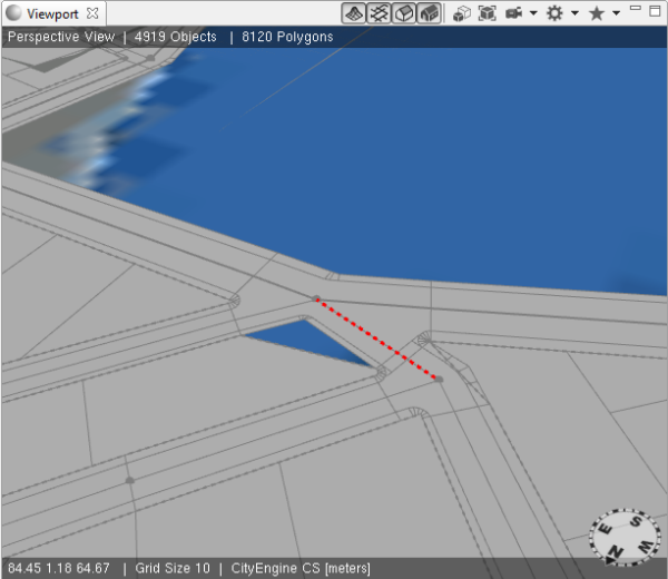
- Select the objects around the conflicting region. It doesn't matter if shapes or other object types are also selected.
- Click the Cleanup Graph tool on the toolbar.
The Cleanup Graph dialog box appears.
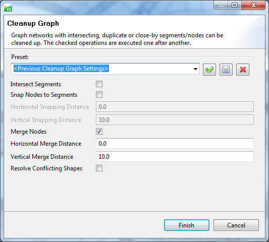
- Explore the settings, and read the Cleanup Graph tool documentation in the help.
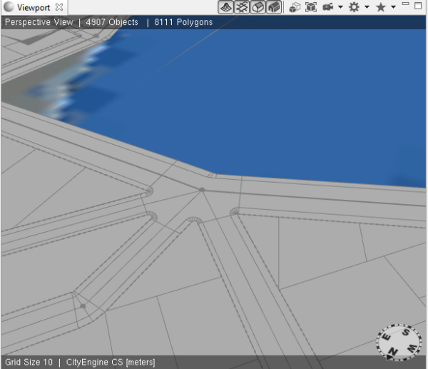
- Your network is now cleaned up, similar to the following screen shot:
Align objects
In reality, streets usually follow the surface of the terrain or where buildings are placed on the terrain. It’s rare that newly-created objects in a scene are directly aligned properly—for example, after importing 2D GIS data—so specific alignment tools are a necessity. CityEngine provides a series of commands to align certain object types to others.
The common alignment types are shown in the following table:
| Object | Alignment type | Example |
|---|---|---|
| Graph segments | > Terrain | Projects street segments onto the terrain |
| Static shapes * | > Terrain | Projects footprint shapes onto the terrain |
| Terrain | > Shapes | Aligns the terrain to shapes (street bank, etc.) |
Note:
*Shapes that are manually drawn or imported are called static shapes. CityEngine’s own system to create shapes—Dynamic City Layouts—creates shapes dynamically, thus they’re called dynamic shapes. An important detail is that dynamic shapes cannot be aligned with the alignment tools. Since dynamic shapes are created as children of (dynamic) blocks (the same is true for streets), the Block Subdivision parameters contain a specific parameter for the alignment. Additional information about Block Subdivision can be found in the following section in this tutorial.
- Select all graph segments in your scene.
- Click the Align Graph to Terrain button
 on the toolbar.
 - Choose your terrain as the Heightmap.
- Add an offset of 0.2.
- Click Finish.
In this scene, there are no static shapes, so continue to align the terrain to the shapes you already have.
- Select all the shapes in your scene (it doesn't matter if you also have graph segments selected).
- Click the Align Terrain to Shapes button
 on the toolbar.
 - Open the terrain’s Layer Attributes in the Inspector.
- Toggle the Enable elevationDelta check box a few times.
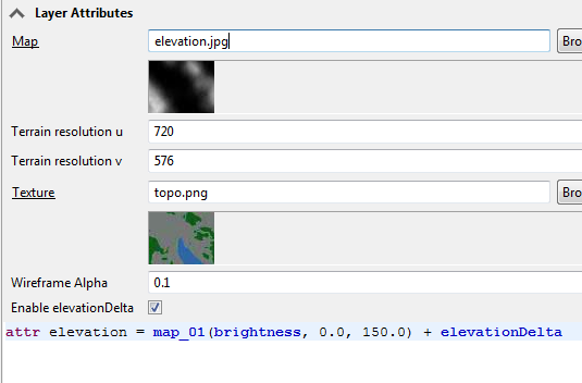
Notice how the terrain switches back and forth between the unaligned and aligned state. This means that somehow the alignment data (the elevationDelta) must have been stored.
- Save your scene.
- Refresh the project’s data folder. (For example, right-click the folder, and use refresh from the context menu).
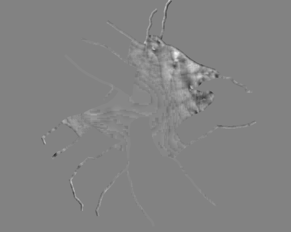
The data folder now contains a new folder that carries the same name as the scene file. This folder and the deltaMap do not exist unless you save your scene after the first terrain alignment.

The (16 bit) delta map that stores the changes (Grey = no change; Black = lower; White = higher) is shown in the following image. The image may look quite different in your example.
Dynamic city layouts
Object types
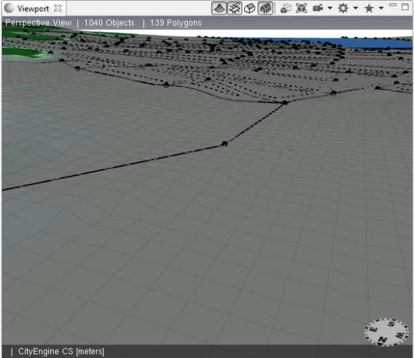
Dynamic City Layouts is a set of tools and functionalities that allow you to quickly create city layouts. The result is a series of shapes, ready for use with CGA rules to create 3D models. The main elements are streets and blocks. Blocks are created if the street center lines physically enclose an area (and the network is cleanly connected). Blocks are represented with a dashed line, which you can select.
Both street segments and blocks have individual parameters that drive the creation of their children, the dynamic shapes.
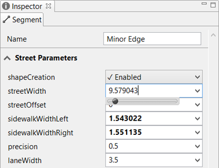
When you explore the streets you've grown so far, you'll find that there are three selectable object types whose parameters drive and influence the shape creation: graph segments, graph nodes, and blocks.
Graph segments
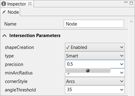
Graph nodes
Graph nodes are the "ends" of a graph segment.
Blocks
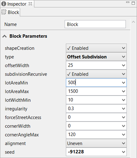
Common to all three object types is the shapeCreation parameter, which lets you determine whether or not those specific object types can produce shapes. For example, you may want to get street shapes, but no subdivision, in the blocks. Again, dynamic shapes are the result of the shape creation of graph segments, graph nodes, and blocks.
You are now ready to do the following:
- Explore all the parameters of the different object types.
- Create some roundabouts, and edit their radii.
- Create some cul-de-sacs.
You'll now focus on the Block Subdivision. Each Subdivision Algorithm has its own parameters and creates a specific pattern.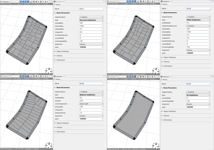
Note:
Shape Creation is a purely interactive task, using Dynamic City Layouts. Shape Creation and Block Subdivision are tasks that have nothing to do with CityEngine’s rule system (CGA). The shapes must first exist (be created) before a CGA rule can be assigned to the shapes for the final generation of the 3D models.
Nevertheless, there is the option to subdivide a full block shape (or any other parcel shape) using CGA.
Streets–Create
In addition to the option of importing graph segments, CityEngine provides two tools on the toolbar dedicated to the creation of street graphs: the Freehand Street Creation and Polygonal Street Creation tools.
- Use both tools to draw some streets.
- Go to Graph > Street Creation Settings.
The Street Creation Settings dialog box appears. This dialog box lets you define your street brush.
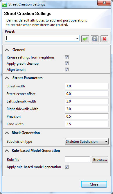
- Explore the Street Creation Settings options, and draw some more streets.
Curved segments
To create streets with curved segments, complete the following steps:
- Select some street segments.
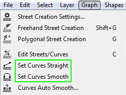
- Explore the Graph > Set Curves Straight and Set Curves Smooth commands.
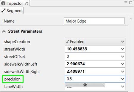
When individual graph segments are selected, you can also edit the precision parameter to set the precision of the subdivision (number of segments) for curved streets. Keep in mind that curved streets produce many polygons; it's best to keep them at a minimum.
Streets–Edit
- Click the Edit Streets/Curves tool on the toolbar or press C for the keyboard shortcut.
- Edit the widths of some streets and sidewalks.
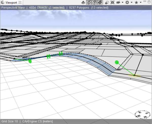
- Edit some tangents. Depending on the viewing angle, only the horizontal or vertical tangents can be edited.
Streets–Generate a model
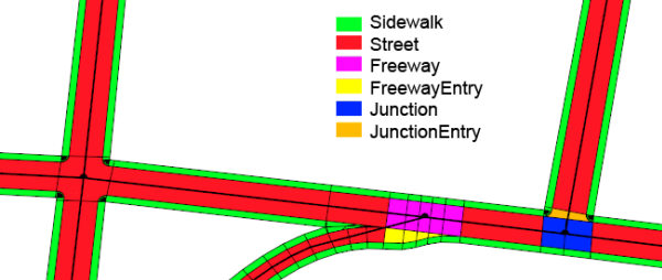
- Explore the StartRules of the streets you created in the Inspector. There are five types (you need to change the type parameter of some street nodes to find them all).
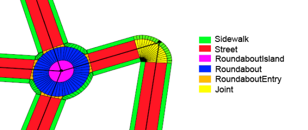
- Assign the provided Street Construction Simple.cga rule to all streets, and generate the models.
- Continue editing the streets while the models are being regenerated on the fly.
Street pattern examples
Workflow examples as impressions
- Create a separated single street.
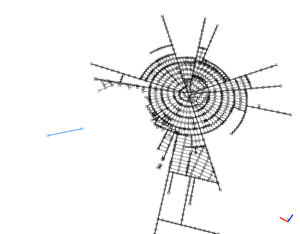
- First growth phase with raster pattern.
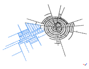
- Second growth phase with raster pattern.
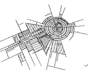
- The two networks are connected.
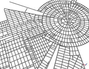
Parameter sets
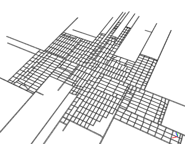
- Raster pattern.
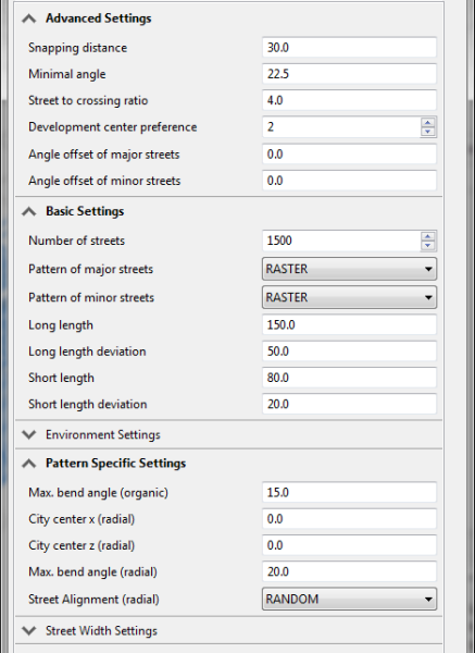
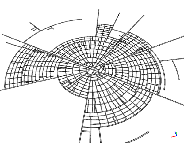
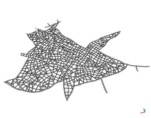
- Radial pattern.
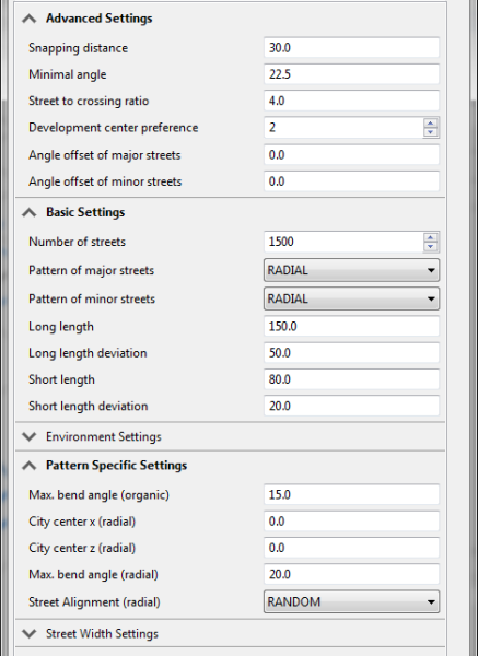
- Organic pattern.
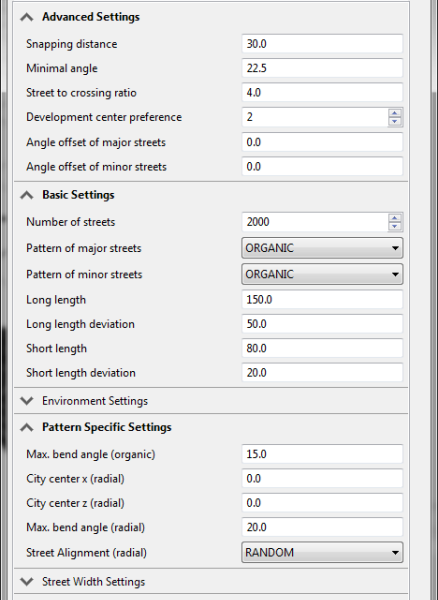
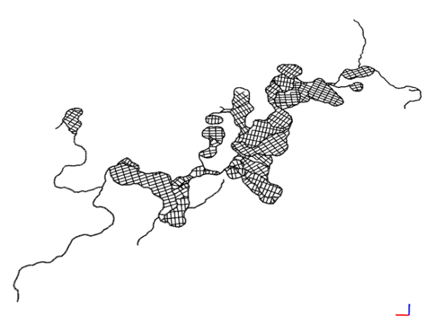
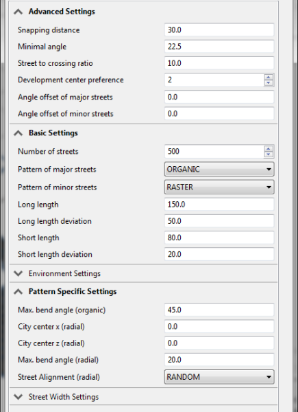
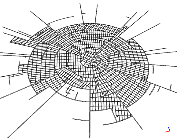
- Radial major streets with raster pattern on minors.
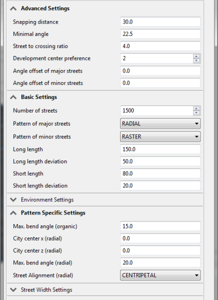
- Organic circle pattern.
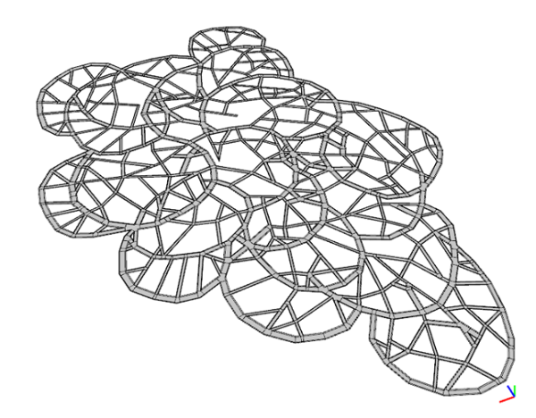
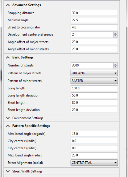
- Honeycomb style.
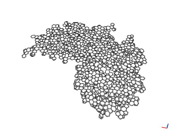
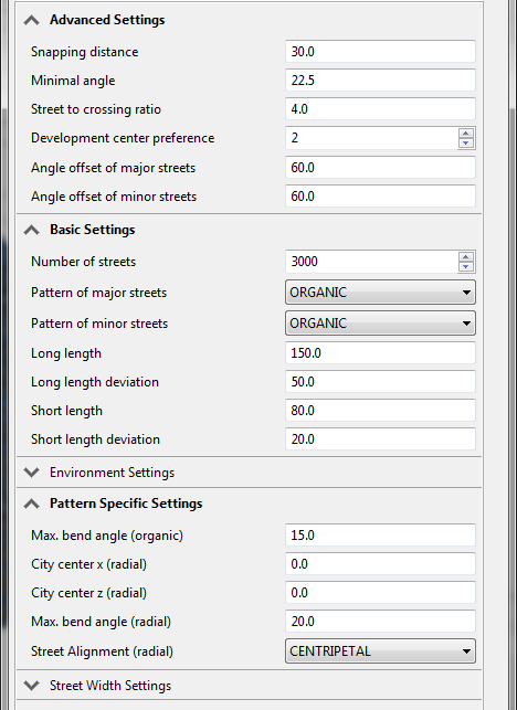
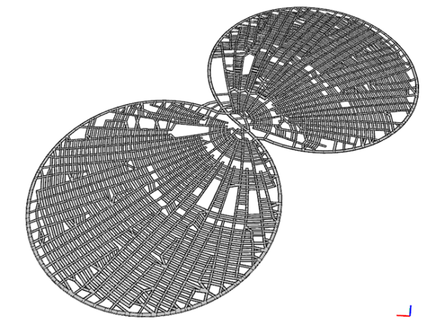
- The Glasses style.
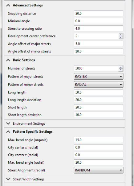
- Organic distribution of rasters.
