Viewshed analysis identifies the cells of a surface raster that can be seen from the location of an observer. The Geodesic Viewshed tool performs viewshed analysis to produce a viewshed raster. This tool can be used as part of a workflow in which you can interactively select observer locations and have the visible area for that location displayed. This topic explains how to configure the tool and use its output to accomplish that task.
Create the observer viewshed output
There are two types of visibility analysis that can be done with the Geodesic Viewshed tool. One records the degree of visibility each cell on the surface has to the observers. The other records the observer locations that are visible from each location on the raster surface. With this type, you can also create a table that lists the individual observers for each region of visibility.
Types of viewshed analysis
The type of viewshed analysis that will be performed by the Geodesic Viewshed tool is set by the Analysis type parameter.
For the Frequency option, the output raster records for each surface cell the number of times that it can be seen by the input observation locations. For the Observers option, the output raster encodes the observer points that are visible from each raster surface location.
Create the viewshed output
In the Geodesic Viewshed tool, specify the input surface raster and the input feature dataset that contain the observer locations. Set the Analysis type parameter to the Observers option. This will activate the Output observer-region relationship table parameter. Provide a name for this output table, and run the tool.
When the tool completes, two outputs will be created. The output raster records the regions of input surface cells that are visible to the observer locations. In the output table, the Region field records the cell values of the regions in the output visibility raster. The Observer field records the feature ID of the observers locations that see the cells in that region.
Relate the tables
You now have a visibility raster and the observer-region relationship table. Next you will set up relates to define the link between the input observer locations and the output visibility raster.
Note:
Before starting the steps below, configure how the relates are set. On the Selections tab of the Properties dialog box of the feature layer or stand-alone table, locate and check the Automatically select related data check box. Do this for both the input observer locations feature layer and the output observer-region relationship table view.
See the following for additional information:
- Introduction to joins and relates
- Automatically select related records
- Selection options
- Select features interactively
To define the two relates, complete the following steps:
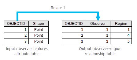
- Use the Add Relate tool to define a one-to-many relate between the input observer features and the output observer-region relationship table.
The following table lists the parameter names and the setting to use for each:
Parameter Setting Layer Name or Table View Specify the input observer features layer name.
Input Relate Field Select the OBJECTID field.
Relate Table Specify the observer-region relationship table name.
Output Relate Field Select the Observer field.
Relate Name Provide the name to use for this relate.
Cardinality Select the One to many option.
The following illustration shows an example of how the data components are related in this step:

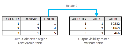
- Use the Add Relate tool define a one-to-many relate between the output observer-region relationship table and the output visibility raster.
The following table lists the parameter names and the setting to use for each:
Parameter Setting Layer Name or Table View Specify the observer-region relationship table name.
Input Relate Field Select the Region field.
Relate Table Specify the output visibility raster layer name.
Output Relate Field Select the Value field.
Relate Name Provide the name to use for this relate.
Cardinality Select the One to many option.
The following illustration shows an example of how the data components are related in this step:

Interactively select viewsheds
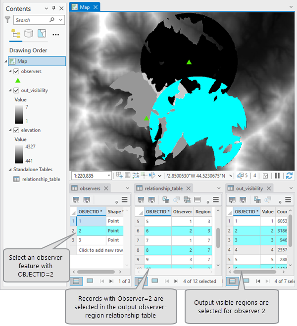
Once the relates are established, you can identify the viewshed for any given observer feature by selecting it from the map display or from the feature attribute table. The corresponding visible regions on the output visibility raster will be automatically selected and highlighted in the map display.
The following image is an example of the connection between selections:
