The ortho mapping workflow, described below, involves the following steps:
- Create an ortho mapping workspace.
- Optionally, measure fiducials.
- Perform block adjustment.
- Optionally, input ground control points.
- Finalize the block adjustment.
- Optionally, update the DTM.
Once this workflow is complete, you can generate orthomosaics or DEMs, or use the image collection directly.
Information about the standard workflow for each step can be found in Ortho mapping in ArcGIS Pro. Below, find recommendations and troubleshooting tips for processing historical images.
Create an ortho mapping workspace
After you have built the Cameras and Frames tables, use the ortho mapping wizard to create a workspace using the Aerial – Scanned option. Options for creating Cameras and Frames tables include the following:
- Compile the tables in either CSV format (before working in ArcGIS Pro) or ArcGIS table format, and load those tables when prompted by the ortho mapping workspace creation wizard.
- You can prepare these tables before creating your workspace using the Build Frame and Camera Tables tool.
Note:
While creating an aerial scanned workspace, it is recommended that you select an appropriate DEM source on the Data Loader Options page. This will create a proper DEM link in the Raster Function chain of the mosaic dataset and update the image as soon as block adjustment is successful. Without a DEM, even if the block adjustment results are good, it will not update the viewer and the dynamic mosaic will appear incorrect.
Learn more about creating an ortho mapping workspace for scanned aerial imagery in ArcGIS Pro
Measure fiducials
Once your ortho mapping workspace has been created, it is recommended that you perform fiducial measurement to align each frame of film with the calibrated camera model. For this step, you’ll use the Refine Interior Orientation button on the Ortho Mapping ribbon.
Learn more about refining interior orientation using fiducials.
Continue below for details regarding fiducial measurement in these two cases.
Measure when camera coordinates for fiducial locations are known
If you entered known fiducial coordinates in the Cameras table, the Refine Interior Orientation interface will appear. You will have one entry in the table for either (or both) edge or corner fiducials. You’ll pan and zoom in the upper window to navigate to a representative fiducial location and capture a template (sample image) for the fiducial. More information can be found in the Refine interior orientation using fiducials.
When your Cameras table includes the known fiducial locations (in microns) from the camera calibration report, complete the following steps for fiducial measurement:
- Define a template for a single fiducial at the position identified by the template type (the left middle fiducial in the following example).

- Use the Compute button to measure fiducials in all other images.
- Visually check the accuracy of the computed results.
- Apply the measurements to the images.
Note:
It is recommended that you capture a very small area around the fiducial. The tool may fail if you capture a large area.

After you have created a template image for one corner or side fiducial, you can click Compute Fiducial Coordinates to measure all of the images in your workspace.
Note:
Depending on the state of your workspace, you may see a blank view at the top of the fiducial menu if the view is zoomed in too far. In this case, use the World button to zoom out to the full image in the upper view, and navigate to zoom in to a fiducial as necessary.

Measure when camera coordinates for fiducial locations are unknown
If you do not have a camera calibration report, you may not be able to enter the known fiducial coordinates into the Cameras table. Starting with ArcGIS Pro 2.6, the Refine Interior Orientation interface allows you to proceed by navigating to capture the template image for all fiducials in one group (for example, all four corners or all four edges). If your camera includes both edge and corner fiducials, it is recommended you capture all eight.
In this case, the bottom of the user interface will show eight entries in the table for the possible fiducial locations. You’ll need to select one location at a time, navigate to the fiducial, and then capture an image of each. Once all measurements are completed for one image, you can select Compute Fiducial Coordinates and ArcGIS will first calculate the fiducial locations in the camera coordinate system, and perform the image file fiducial measurement on all images in the collection.

When your Cameras table did not include the known fiducial locations (or you did not have a camera calibration report), complete the following steps for fiducial measurement:
- Capture a template for all middle and corner fiducials for a single image.

- Select Compute to measure all other photos.
- Visually check the accuracy of the computed results.
- Apply the measurements to the images.
Perform aerotriangulation and block adjustment
The next step in ortho mapping is to run aerotriangulation to automatically find tie points between images in overlapping areas and a block adjustment to resolve and later to improve the accuracy of the interior and exterior orientation.
Learn more about performing block adjustment in ArcGIS Pro
The first time you run the Adjust tool, the software will automatically generate tie points while performing a simultaneous, multistation relative orientation of images in the block. After tie points have been found, re-running Adjust (for example, after entering ground control points) will be much faster since only absolute orientation is performed.
If you are using the ortho mapping ribbon interface, the settings applied for tie point collection and block adjustment are predefined based on the image type (in this case, scanned aerial photos) as well as assumptions about the accuracy of the initial orientation data. If you need more detailed control over these steps, you can run individual geoprocessing tools, including Compute Block Adjustment to calculate new values for the exterior orientation and Apply Block Adjustment to apply the new values within the mosaic dataset.
After running block adjustment, check to verify that your images are at the correct scale and in the correct positions. Also check to verify that all images were successfully processed. If you find some images were removed from the block, you can click Tie Point Editor to restore them to the project. Add tie points from any rejected images to appropriate neighbor images, and re-run the block adjustment.
The image collection in the map may not be accurate enough for a final product. If not, proceed to adding ground control points (GCPs).
Note:
ArcGIS Pro can perform camera calibration to compute lens distortion values. For professional mapping cameras, distortion values are so small that this can be ignored for many projects, but you may want to see the radial distortions. By checking Perform Camera Calibration, distortions are automatically computed. If you run the geoprocessing tool instead of using the ortho mapping ribbon, you must define the CameraCalibration Adjustment option as 1 to activate the option to compute distortion coefficients.
Apply ground control
Using accurate ground control is recommended to ensure the best accuracy in your final products. If you have information regarding control points recorded at the time of the film flight, refer to Add GCPs to your ortho mapping workspace for information about how to ingest a table of control points and then link the points to the images.
Some film projects may be very old or poorly documented and do not have high-quality control points. In this case, refer to the following sections.
Options for the best available ground control
For best accuracy, you must apply ground control in the block adjustment process.
You need both a source of control and to be able to identify the control point locations in the images. Depending on the age and scan quality of your imagery, finding photo-identifiable points may be challenging.
Note:
The interface to enter GCPs is not enabled until after an initial block adjustment.
Sources of horizontal control
Optimum ground control is collected using a modern GPS receiver on permanent objects visible in the historical photos. Examples could be corners of concrete sidewalks or, in natural terrain, it may be possible to locate large rocks visible in the photos.
You may extract control from an orthomosaic with known accuracy. If available for your project area, you can load a suitable reference orthomosaic into the map and add control points to your historical imagery using this imagery for a visual reference.
One recommended source for projects in the United States is to load the NAIP image service from ArcGIS Living Atlas. There are different years available, so you may need to view the oldest NAIP layer.
Many users also reference the Esri World Imagery basemap to extract control points. Since Esri collects this imagery from a variety of sources, the horizontal accuracy of this imagery is not reported. Consult Imagery with Metadata for more information about the accuracy of the World Imagery basemap.
When extracting control from existing imagery, measure points that are on the terrain, not elevated features such as tops of buildings. It is also better to select points that are on flat terrain—they are likely to be more accurate and can also possibly be used as vertical control.
If you are processing photos from multiple years, start by processing the most recent date and applying your best available control. Then, use the orthomosaic output you just created as control for the previous year; continue in this manner until all your images are processed. For example, you would process 2020 imagery, use it as control for 2019, and then use the processed 2019 imagery as control for 2018.
Sources of vertical control
Note that control points extracted from the map will determine z-values using the ground elevation source currently loaded in the map. By default, the ortho mapping workspace loads the World Terrain service into the map, and this layer provides z-values for control points.

If you have an alternative terrain dataset for this area, it can be added into the map prior to control point extraction. Click the Add Data button and select Elevation Source.

It’s important to ensure correct vertical reference for GCPs. If you are using an alternative DEM for vertical control, ensure the units are correct for your project coordinate system (typically meters versus feet). If you need to rescale vertical units, you can add an arithmetic raster function to apply a vertical multiplier to the DEM values.
Also be sure to determine if the vertical reference for your DEM is a geoid (sea level, to provide orthometric height) or ellipsoid. It is uncommon for a DEM to reference ellipsoidal height, but if you have this case, you can add an arithmetic raster function to apply a vertical offset to the DEM values.
Enter control points
With a suitable reference image in the map, you’ll need to enter and link to control points.
For each control point added into the table, selecting that control point will populate the lower portion of the user interface with the list of images that may contain that point. Control points are measured or linked in this graphical user interface to show the pixel location for the point in each image.
When the first image is linked, ArcGIS Pro will search in neighbor images and automatically link other images if possible. Those images successfully linked will show a blue plus sign in the GCP user interface—for example, in the following screenshot, all images were automatically linked.
Note:
It is important to ensure that the same terrain model used for extracting the ground control is used to generate the ortho photos. This does not apply if a DEM will be generated from the adjusted images.
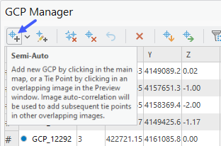
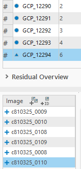
It’s recommended that you view the location of each GCP link to ensure accuracy—each link may be edited if necessary.
The number of control points needed depends on the accuracy required and the density of the tie points that were collected, which is affected by the quality of the imagery, image content, and overlap between frames. In traditional photogrammetric projects, ground control would be placed approximately every four frames along strip images. It is especially important to have control at the extremities of a project, since this is where errors will quickly extrapolate. In many cases, it may be helpful to add the ground control in an iterative manner. First, add a few ground control points, and then do the block adjustment. This should improve the accuracy of the block and allow you to find additional control points. Ground controls must be determined and measured in overlapping areas of the block being processed.
Note:
Currently, the GCP Manager allows you to define points to be used for control or as check points. If you want to use some control only as Horizontal control, set the z-accuracy to zero. This will not apply adjustments to z-values and will only report residuals in x,y. The same may be done for vertical control by setting x,y accuracy to zero.
Use check points to measure accuracy
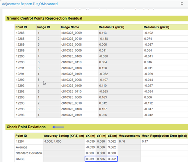
Note that control points are used to control the block adjustment process. Although the processing report will show residual errors for the calculated locations of these points, this does not equate to the overall accuracy of the final product.
To generate an independent measure of accuracy, a separate set of points, called check points, are used to measure errors after the block adjustment. (The check points are not used within the block adjustment calculations.)
Presuming you can identify enough suitable points, enter all GCPs into the ortho mapping project. After the measurement (linking) process is completed, but before running the final block adjustment, it is recommended that you change some of the GCPs to check points. To do this, select a single GCP or group select multiple GCPs and right-click to change mode.

Check points are then withheld from the block adjustment and a summary of project accuracy is reported for check points in the processing report.
Proceed without ground control
If it is not possible to apply suitable control as described above, you can omit the ground control step, perform a free adjust block adjustment, and create an orthomosaic that may have limited accuracy.
In this case, it is better to use a DEM generated from the adjusted images to support orthorectification than it is to use an existing terrain model that may have little relation to the image locations. You could then use georeferencing tools to adjust your orthomosaic to ensure the correct scale and achieve best alignment with your GIS data (or an Esri basemap).
Finalize the block adjustment
After control points have been entered and linked to photos, you will need to re-run the block adjustment to apply the control to the project, and, optionally, update the image collection terrain model to improve the alignment of the dynamic mosaic.
Note that when the configuration of the ortho mapping workspace is set to aerial scanned, the elevation source (DTM) set at workspace creation is not applied within the mosaic dataset until you specifically define it.
Update the image collection terrain model
Even if you've got a good block adjustment result, the resulting dynamic orthomosaic may still have poor accuracy until you update the image collection with a suitable DTM.
The accuracy of the DEM has a significant effect on the accuracy of the resulting orthophotos. In the nadir region of each frame, the accuracy of the DEM has limited effect, but at edge of the frame the error in the orthophoto can match the error in the terrain model. Even though a pre-existing DTM can be used to support orthorectification, it is recommended to use a DTM extracted from the adjusted images for best results.
Use a preexisting DTM
If you already have a suitable DTM, you can use that to update the image collection. In many cases, especially for smaller-scale imagery, you can export a local DTM file from the World Elevation service in ArcGIS Living Atlas to use.
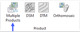
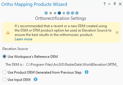
On the Ortho Mapping menu on the ribbon, in the Product category, click Multiple Products, and select only the Orthorectify Images option.

On the next page, either select Use workspace’s reference DEM (if you defined the desired final DTM at project setup), or navigate to an appropriate bare earth DTM (such as World Terrain available from ArcGIS Living Atlas).
Note:
The imagery must be aligned with the DTM to generate a good quality orthorectified result. The World Terrain service is a suitable DTM for a scanned film project, but if your mosaic is misaligned from its proper location more than 10 meters, you must have control points in your project or consider extracting a DTM from the imagery.
Generate and use a DTM from the imagery
If the accuracy of the existing terrain model is not sufficient or if the terrain has changed significantly, you can use ortho mapping tools to generate a terrain model. The advantage of generating and using a terrain model from the imagery after block adjustment is that the accuracy of the resulting ortho imagery will not be related to inaccuracies in the original terrain model.
In this case, refer to Extract DEMs from the imagery, where you can use the custom menu to first extract a DEM (choose type=DTM) and then apply it to the image collection.
If you are satisfied with the results after defining the image collection DTM, you are ready to use the existing mosaic dataset directly or generate persisted output products.