The Tools page allows you to accurately georeference Autodesk Construction Cloud (ACC) document extents, document models, project issues, and project boundaries on a map and scene. It also allows you to view the historical record of all tool runs for the ArcGIS GeoBIM project.
Note:
See Security requirements for ArcGIS GeoBIM before you configure the geoprocessing tools.
Tools tab
The Tools tab is used by creator or above user types to ingest source project data from ACC into their ArcGIS GeoBIM feature service. It allows organizations to persistently monitor progress over time and assists in decision-making as plans and designs change or issues arise. Run the geoprocessing tools as engineering documents and issues are added, updated, or removed from the ACC project. This ensures that your team is always working with the most up-to-date information.
The Tools tab contains several configurable options:
- Select Autodesk project folders
- Add Document Extents
- Add Document Models
- Add Project Issues
- Add Project Boundaries

The following table lists the elements of the Tools tab and includes a description of their purpose:
| Element | Description |
|---|---|
1 | Select the Tools tab to view, configure, and select the geoprocessing tools to run against your ACC project data. |
2 | Select the History tab to display the historical record and metrics of all tool runs. |
3 | Select the Select Folders button to view the Autodesk projects and folders included in your ArcGIS GeoBIM project. Customize the folder selection to synchronize only the data that is pertinent to your project teams. |
4 | The Add Document Extents tool creates 2D polygon features representing the extent of engineering documents on the earth with links to the source ACC files. Configure this tool to include only the specific file formats you want to work with, add thumbnails to your design files, or set the WKID of the project. Note:The Add Document Extents tool can not be disabled. |
5 | Select the Add Document Models tool to create simplified, performant 3D models from detailed geometry Revit and IFC documents. These models are then placed on the earth in a project web scene with links to the source ACC files. |
6 | Select the Add Project Issues tool to add issues from ACC as point features on a map based on their placement in linked engineering documents. Note:By default, the Use project address setting is enabled to locate issues that lack a linked document. These issues are placed at the project address set in your BIM project. |
7 | Select the Add Project Boundaries tool to create 2D polygon features on a map based on aggregated document extents. Configure this tool to select the preferred output shapes for your BIM Projects layer. |
8 | Select the Run button to start the tools run after you have finished configuring the selected folders and tools. Once the job starts to process, the Cancel button allows you to force the run to end. Note:Once the tool run has finished, a success or failure message will be displayed. Go to the History tab to analyze more details and metrics related to each tool run. |
History tab
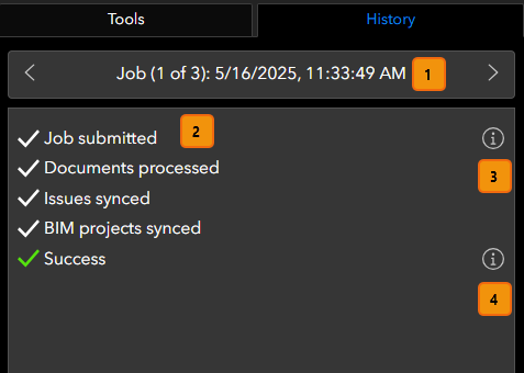
The History tab displays the sequence of tool runs. This tab allows you to view and analyze the historical record and status of all submitted jobs.
| Element | Description |
|---|---|
1 | The Job navigator arrows allow you to browse through all submitted tool runs. Each job will have a sequence number, as well as date and time of submission displayed in the navigator. |
2 | The Job status text identifies which tools were selected per run and whether the job finished successfully, failed, was canceled, or is still in progress. Note:If the job failed or was canceled, the check mark icons are replaced with error icons and the Success string is replaced with either Job failed or Job canceled. |
3 | Select the View Job Parameters button to view the selected tools and their setting configurations. |
4 | Select the View Job Summary button to view metrics like date and time of job completion, elapsed time of the tool run, and the total number of features ingested for each selected tool. |
Job failures
If your tools run failed or succeeded with errors, you will see a list of all errors experienced in the View Job Summary window under Job Errors. The error will identify the problematic design file and, in some cases, provide a URL to the location of the file in ACC.
To view a more detailed log of the errors encountered, select the Download Error Report button at the bottom of the History tab. This will initiate the download of a .zip file containing a text file listing all documented errors. Also, a Send Report window will display in ArcGIS GeoBIM, from which you can send the error report through to technical support.