The 3D Viewport is your main interaction tool with the CityEngine scene besides the Scene Editor. You can have any number of open viewports. Select Window > New Viewport from the main menu to create a new viewport.
To learn more on how to navigate in 3D, transform scene objects, and work with bookmarks, see scenes.
Viewing modes and display settings
The 3D Viewport offers many viewing modes and display settings. These options are accessed in the top toolbar of the viewport window.
Active scenario
You can use the Scenario tool  to change the active scenario for the given Viewport.
Layer type visibility
The layer buttons determine which layer types are visible on a per-viewport basis. Selective rendering of layers can be used, for example, for rendering shapes in one viewport and geometries in another.
| Item | Function | Shortcut |
|---|---|---|
| Isolate the current selection, hide unselected objects. Note:Terrains and Analyses layers will still be visible even if not selected. | Press I |
| Toggles attribute map layer visibility for this viewport. | Press F9 |
| Toggles graph network visibility for this viewport. | Press F10 |
| Toggles shape visibility for this viewport. | Press F11 |
| Toggles model visibility for this viewport. | Press F12 |
| Toggles analysis visibility for this viewport. |


Camera and viewport settings
You can click the View settings tool  to change settings such as camera or textures. The View settings tool has the following options:
| Item | Function | Shortcut |
|---|---|---|
10mm fisheye lens (121° FOV) | Type of lens and FOV (field of view). | |
18mm ultra-wide lens (90° FOV) |
Type of lens and FOV (field of view). | |
24mm wide-angle lens (73° FOV) |
Type of lens and FOV (field of view). | |
35mm standard lens (54° FOV) |
Type of lens and FOV (field of view). | |
50mm standard lens (39° FOV) |
Type of lens and FOV (field of view). | |
70mm telephoto lens (28° FOV) |
Type of lens and FOV (field of view). | |
135mm telephoto lens (15° FOV) |
Type of lens and FOV (field of view). | |
Parallel projection view |
Type of lens and FOV (field of view). | Press P |
Wireframe | Renders the scene contents as the Wireframe of the face borders. Tip:To see the wireframe of terrains, select them in the Scene editor and enable the Wireframe option in the Inspector. | Press 4 |
Shaded | Renders the scene contents with colors but with no textures. Note:This also means that no opacity maps are applied and some otherwise transparent parts are rendered opaque. | Press 5 |
Textured | Renders the scene contents with colors and textures. | Press 6 |
Wireframe on Shaded/Textured | Enable/disable an overlay like the wireframe render mode but on top of the rendered elements. | Press 7 |
Shadows | Turns shadows on or off. Note:Note that enabling shadows on large models may considerably affect rendering performance. | Press 8 |
Ambient Occlusion | Enable/disable ambient occlusion rendering (ambient occlusion). | Press 9 |
On-camera light | Toggles the sun position between the specified location and straight behind the camera. | Press L |
Single-Sided Lighting |
|
|
Backface Culling | Enable/disable backface culling. With backface culling enabled, only faces facing the camera are rendered. |
|
Information Display | Toggles the information display. The information display provides statistics for the current scene such as number of objects and polygon count. | Press D,D |
Axes | Toggles rendering of the axis visualization in the bottom left corner. Note:The coordinate system can be switched in View Coordinate System. | Press D,A |
Compass | Toggles rendering of the Compass in the bottom right corner. | Press D,C |
Grid | Toggles rendering of the Grid at elevation 0 for reference. | Press D,G |
Bookmarks gizmos | Toggles visibility. Toggles rendering of small cameras for the Bookmarks locations. | |
Handles | Toggles handles visibility. | |
View Coordinate System |
Choose a Coordinate System for the Navigation Display and the axis visualization |
|
Note:
Press D to open the shortcut table for display of Information, Axes, Compass, and Grid
Render modes
The Viewport can render its contents in the following modes:
Wireframe — All edges of objects are drawn as lines. There are no filled polygons so you can "look-through" the objects. The wireframe mode can be activated by selecting the Wireframe button or pressing 4. | 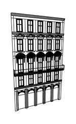 |
Shaded — All polygons are filled with the object color. No texturing takes place. The shaded mode can be activated by selecting the Shaded button or pressing 5 | 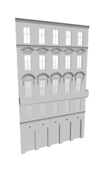 |
Textured — All polygons are filled with textures and object colors. The textured mode can be activated by selecting the Textured button or pressing 6. | 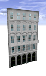 |
Wireframe on Shaded/Textured — Overlay wireframe independent of the viewing mode by enabling Wireframe on Shaded/Textured in the View Settings menu or pressing 7. | 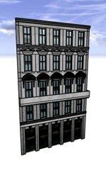 |
Viewport settings are stored per-viewport together with your scene data. This means that when you reopen a scene, you get exactly the same viewport settings as when you were saving the scene.
Note:
Global viewport settings can be changed by selecting Edit > Preferences > General > Viewport from the main menu, see also Viewport preferences.
Viewport context menu
Depending on the selection, the context menu contains different entries for different objectives.
Frame (F) | Frame the selection (or the whole scene if selection is empty). |
Select Objects in Same Layer | All objects in the same layer(s) are selected. |
Select Objects with Same Rule File | Selects all objects having assigned a rule file that is present in the source selection. |
Select Objects with Same Start Rule | Selects all objects having a start rule that is present in the source selection. |
Select Continuous Graph Objects | This method can be used to select graph segments that are continuous, e.g. if they together define one street. The search for continued segments starts at the source selection. |
Copy to scenario | Copy objects from one scenario and to another scenario. |
Move to scenario | Move objects from one scenario to another scenario. |
Additionally, you can Cut, Copy, Paste, or Delete in the context menu. Finally, you can also toggle the full screen mode for this Viewport.
Tip:
If you have a 3D mouse installed you can change the mouse options here. These options are applied for all viewports.
Make names unique
Names of generated objects in a CityEngine scene are not automatically unique. In some cases, unique names are required. This can be achieved by clicking Edit > Make Names Unique Tool.
All selected scene objects are enumerated and renamed in ascending order. The delimiting character can be chosen.
Note:
This is a one-time operation. Once you modify your scene (add scene objects), there might be new shapes with non-unique names again.