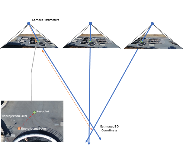
During processing, Drone2Map uses the GPS metadata from images, camera parameters from the camera database, and tie points obtained from automatic feature matching to triangulate the 3D coordinates of a scene. Ideally, the rays from the triangulated tie points would converge on a single 3D coordinate. However, there is often uncertainty in the location of the triangulated points, called the reprojection error.
After the points have been triangulated, a bundle adjustment process optimizes the position of the 3D coordinates by adjusting the estimated 3D coordinates using a best fit solution that minimizes the reprojection error, while staying within the defined camera parameters. The result is a reconstructed scene with a strong relative accuracy and an absolute accuracy that is dependent on the accuracy of the georeferenced images.

Sometimes projects require an absolute accuracy that is greater than the georeferenced images can provide. For better accuracy, you can add control to your project. Control refers to points with known x,y,z ground coordinates, often obtained from ground survey, and is used to increase the absolute accuracy of the project.
Control points add positional constraints to the bundle adjustment process, which further optimize the best fit solution. It’s important to note that even with high-accuracy control, the best fit solution from the bundle adjustment process must adhere to the camera parameters. In some cases, the output location of control points may deviate from their collected locations. Proper image collection and control placement minimizes these discrepancies.
Image quality
Poor image collection techniques can cause error propagation that reduces the effectiveness of your control. The absolute accuracy of your model is dependent on the accuracy of your measured control, and how well the bundle adjustment process can minimize the error in the best fit solution. Factors that can introduce error in the bundle adjustment process include insufficient overlap between images, blurry images, inconsistent or poor lighting conditions, vegetation, and more. Therefore, maximizing the absolute accuracy of your project begins with good image collection techniques.
Note:
- Best practices suggest that the accuracy of control should be three times better than the ground sample distance (GSD) of the final product. However, due to the high resolution of commercial drone imagery, this guideline may be difficult to achieve, resulting in products with slightly lower accuracy than the control.
- The absolute accuracy of your model cannot be higher than the accuracy of your control. With good image collection techniques and proper control placement, the absolute accuracy of the model is typically
in the horizontal direction, and1 – 3 x GSD
in the vertical direction.1 - 4 x GSD
Distribution of ground control points
In addition to proper image collection techniques, the amount and distribution of control in your project play an important role in the final absolute accuracy of the model.
Adding control constrains the bundle adjustment process to the measured location of the control. As you move radially away from the center of a control point, the accuracy begins to deteriorate. Distributing control evenly throughout the project in a triangular network to reduce the distance between control ensures a consistent accuracy across your model. Placing control in a single line, such as along the edge of a road or along a corridor, results in geometric warping of the end products.
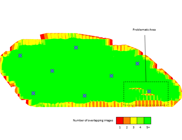
The more a control point appears in multiple images, the better the results. It is recommended that you avoid placing control at the edge of the project, where image overlap is reduced. Instead, offset control from the edge toward the center of the project to maximize overlap.

There is no consensus on the number of control points to use in a project. However, more control increases the absolute accuracy of the project, with diminishing returns as the absolute accuracy converges on
1 - 3 x GSDNote:
- You must include at least three control points for them to be used during processing. A minimum of 5 to 10 control points is recommended.
- Place control on flat terrain at ground level, away from features that may obstruct the view from the camera, such as vegetation or structures.
- Use surveyed control targets for best results. If these are unavailable, objects that are identifiable in the imagery (secondary control points) can be used as control.
Processing settings
The tie points that are obtained from automatic feature matching during initial processing are used to estimate the 3D coordinates of the scene, which are then used in the bundle adjustment process to optimize the model. To maximize the absolute accuracy of your products, it is important that the individual keypoints that make up the tie points be as accurate as possible. To maximize the accuracy of the keypoints, Keypoints Image Scale should be set to Full.

Note:
- In some situations, such as models with dense vegetation, reducing or increasing the Keypoints Image Scale may produce more accurate results. When creating your final products, it is recommended that you start with Keypoints Image Scale set to Full, and reduce or increase the scale if necessary.
- Increasing the Keypoints Image Scale setting improves the accuracy of your products while increasing the processing time.
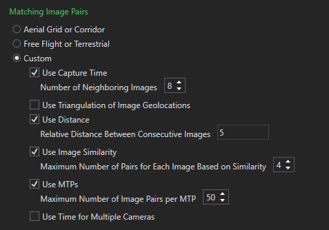
The more keypoints that compose a tie point, the more accurate the estimated 3D coordinate becomes. The Matching Image Pairs setting specifies the images to use to search for matching keypoints. Generally, the predefined Matching Image Pairs settings include enough images to produce accurate tie points. However, it may be possible to increase the accuracy of your products by increasing the values in a custom matching strategy.

Linking control
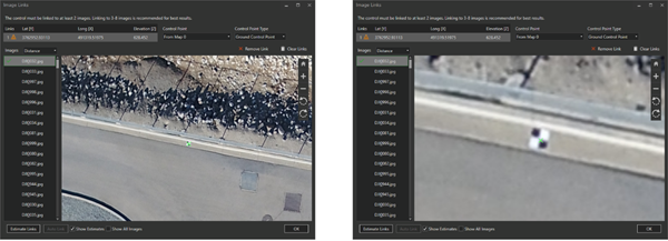
When incorporating control into your project, the location of the control is manually identified in each image through the Image Links Editor. Diligence in marking the precise location of the control in all images correlates with the absolute accuracy of the final products. While this can be a daunting task on projects with several images and control, using the assisted links feature makes this process faster.

Assessing the accuracy of your model
The bundle adjustment process attempts to fit the model to the location of the control. As a result, the accuracy of the product is highest at the control points. As you move outward radially from a control point, accuracy begins to diminish. Therefore, using the control points as a measurement of the absolute accuracy can give superficial results.
Check points can be used to authenticate the overall absolute accuracy of the product. Check points are collected similarly to control points but are not incorporated into the block adjustment process. Instead, control points are used to independently assess the accuracy of the model after processing is complete.
Note:
- As with control points, distribute check points across the entire project.
- Using too few check points can produce inaccurate results.
Sources
Sanz-Ablanedo, E.; Chandler, J.H.; Rodríguez-Pérez, J.R.; Ordóñez, C. "Accuracy of Unmanned Aerial Vehicle (UAV) and SfM Photogrammetry Survey as a Function of the Number and Location of Ground Control Points Used." Remote Sensing. 2018, 10, 1606.