To access the tutorial projects in ArcGIS CityEngine, open CityEngine and click Help > Download Tutorials and Examples in the main menu. After choosing a tutorial or example, the project is automatically downloaded and added to your CityEngine workspace.

This tutorial is a continuation of Tutorial 14a: 2D and 3D Shape modeling in which the fundamental manual drawing techniques are taught. In this tutorial, you will learn more about the tools and options to work with terrain:
- Align shapes and streets to terrain
- Align terrain to shapes
- Edit terrain with brush tools
- Drawing street and shapes on terrain
It is structured into two parts, mimicking typical workflows in CityEngine:
- Prepare the scene context by aligning the footprints and streets to the terrain.
- Create a proposal for redevelopment by preparing scenarios, adding street setbacks, creating massings and adding vegetation on a terrain.
Prepare the scene context
In the following chapters you will look into different strategies for matching streets, shapes and the terrain together. You will learn how to draw streets on the terrain and remove visual artifacts from terrain edits. Bringing the context data in state ready for visualizing the current conditions, performing analysis tasks and designing future interventions.
Align streets and footprints to terrain
To align streets and footprints to the terrain, do the following:
- Expand the Tutorial_14_Polygonal_Modeling tutorial folder in the Navigator window.
- Double-click the 14B_ ModelingOnTerrain.cej file in the scenes folder to open the scene in the Viewport window

The scene contains of three layers:
- Terrain
- Streets
- Footprints
Notice that the streets and footprints are below the terrain; this is a common issue when importing georeferenced data which does not contain height information. In the following steps, you will fix this by moving them onto the terrain. You don’t need to do this manually as CityEngine has the Align Streets to Terrain and Align Shapes to Terrain tools available to complete this task.
Note:
If you want to learn more about how to import data check out the Tutorial 4: Import streets, Tutorial 5: Import initial shapes and Essentials: Work with GIS data tutorials.
- Start by selecting all streets by right-clicking the Streets layer in the Scene Editor window and click Select Objects.

- Click the Align streets to terrain tool
 in the main toolbar to open the Align Streets to Terrain dialog box.

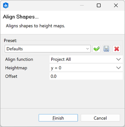
In the Align Streets to Terrain dialog box, you have the option to choose between two options to align the street nodes: Project All projects all selected nodes onto the chosen terrain, while Project Below moves only the nodes which are below the terrain. Since all street nodes are currently below the terrain, it does not matter which option you set.

With the Heightmap option you choose which terrain in your scene the nodes are aligned to. Regardless of how many terrains you have in your scene, there is always the option y=0 which means that all the street nodes are placed on the ground.

In CityEngine, the node shapes are always flat. The height difference between two nodes is evened by the segment shapes. This means that after aligning the street to the terrain, some parts of the street may still be under the terrain. By defining a positive offset this could be fixed. Later in the tutorial, you'll learn how to align the terrain to the street shapes to address this.

- Ensure the Heightmap option is set to Terrain and leave the other options as default.
Click Finish to apply the alignment.

All the streets are now aligned to the terrain.
- In the Scene Editor window, select all the shapes from the Footprint layer.
- Click the Align Shapes to Terrain tool
 in the main toolbar to open the dialog box.
The only difference between the Align Shapes to Terrain and Align Streets to Terrain dialog boxes is the additional alignment options:

The Project All and Project Below functions work the same way but for shape vertices instead of street nodes. Project to Object Average calculates the average of all vertices of a shape and sets them to this value, which can be used to flatten non-planar shapes. The following image shows the differences between the translate options:

When placed on uneven terrain, a building footprint translated to maximum will visibly float; translated to minimum it will sink so that all edges are on or below the terrain; and for translated to average, part of the shape will be above and below the terrain.
- Set the Align function option to Translate to Minimum to avoid gaps which would require further terrain editing; CityEngine applies the same options to the footprints when using Get Map Data. Again, set the Heightmap option to Terrain and click Finish to apply the alignment.

Align footprints with Translate to Maximum
While the Translate to Minimum option works well for most cases, it’s possible that after aligning the shapes, there is a large part of the shape positioned below the terrain. This is a common issue for large shapes on steep terrain. To fix this, do the following:
- Navigate to bottom right side of the scene, or click Align footprints to terrain in the Bookmarks menu
 .
.There you can find two examples in which there are issues with the alignment.


- Select these shapes manually or apply the Shapes to translate to maximum selection set.


- Run the Align shapes to terrain tool again, but this time set the Align function option to Translate to Maximum.

This looks much better.
Align the terrain to footprints
After aligning the footprints with the Translate to Maximum option, some parts of the buildings are not touching ground anymore. To fix this, you can raise the terrain to match the height of the shapes.
- With the shapes still selected, click the Align Terrain to Shapes tool
 in the main toolbar.

When the Add border check box is checked, the alignment is applied to the shape area plus a small offset outside of the shape.

By default, the terrain is aligned vertically between the original and the edited terrain. With the Smooth borders option, you can choose Smooth range or Constant gradient to define the transition method.


- For visually pleasing results, set Smooth borders to Smooth range, Border range to 2 m, and check the Border easing check box.
Leave all the other options as default and click both Apply and Close.

The terrain is now raised around the selected shapes.
- Unselect the shapes and zoom into the building on the left and take a closer look (Bookmark: Terrain smoothing).

You can see that at the transition between the original and edited terrain artifacts are visible.
- Use the Terrain Smooth Brush tool
 to remove artifacts.
After you click the brush, an orange circle appears in the Viewport window indicating the area where the smoothing is applied when you click. When the circle is below the terrain, it is rendered semi-transparent.

- In the Scene Editor window, select the Terrain layer.
Set the Wireframe option to Enabled in the Layer Options section in the Inspector window.

A grid is now rendered on top of the terrain.
- Smooth out the artifacts.
In the Viewport window, click the terrain to apply the smoothing at the pointer location and drag to keep smoothing.

As you can see, the smoothing is too strong using the default settings. Press Ctrl+Z to undo the smoothing.
Fine tune the brush settings in the Terrain Smooth Brush tool options by changing the brush size, strength, and smoothing behavior. The strength depends on the resolution of the terrain.
- For the terrain in this scene, set Strength to 2.5% and reduce Brush Size to 5 m for better control. Position the circle a bit outside of the building and drag along the edge to smooth the steep area of the terrain.

- Continue smoothing where necessary along all building edges where the terrain was aligned.
Your result should look similar to the following image:

Tip:
To smooth along buildings, usually the camera position must be adjusted. When you stop and restart smoothing, a visible border can appear between the new and previous circle. To fix this, use the Continuous smoothing option and set Strength to 0.1%, and smooth again at the affected area.
Great, now everything is in its right place.
Align terrain to streets
When you further inspect the scene, you can see the terrain overlapping the streets in some areas (Bookmark: Align terrain to streets). The reason for this is that the street geometry depends on the height of the nodes. Node shapes have the same height as the node and the height difference between two nodes is leveled out by the lane shapes. To fix the overlapping, you'll use the Align Terrain to Shapes tool again.

- Select all streets in the scene, and click the Align Terrain to Shapes tool .
- Keep the settings from the previous alignment.

- Click both Apply and Close.

Now all the streets are fully visible.
Add a missing street
In case of incomplete data, you may need to add some data by tracing over the underlying map. In this example, there are some streets missing and in the following steps, you'll learn how to draw streets manually on the terrain.
- Navigate to this area above the river (Bookmark: Add missing street).

- Ensure the Polygonal Street Creation tool
 (G) is selected.
 In the tool options, set the Street Configuration option to Neighborhood_Street_6m and turn off the Re-use settings from neighbors toggle button, otherwise the chosen configuration is not assigned when you start drawing a segment connected to an existing street.

- Start with the first click at the center of the curve and trace along the street. Each new node is automatically placed onto the terrain.

- After connecting to the street on the bottom, press Esc to end the drawing mode.
The terrain is automatically aligned to the street shapes based on the latest used settings from the Align Terrain to Shapes dialog box.

Create a bridge
Most of the time, it best to ensure that streets are aligned to the terrain. However, elevated network features such as bridges, viaducts, ramps and piers require a different approach.
- Zoom out a bit further and focus on the area to the left of the previously drawn street (Bookmark: Add a bridge).

As you can see from the terrain the missing street crosses the river.
- Select the Polygonal Street Creation tool .
Set the Street Configuration option to Simple_Street_Generic_12m and turn off the Align terrain and Intersect Segments toggle buttons.

- Start tracing the street from the terrain edge using the basemap image as a guide.

- Connect to the existing street on the other side.

- Finish the street to the end of the terrain map.

- Click the Edit street/curves tool
 and drag the green handle to adjust the curve horizontally to match the lines on the map.
- Navigate to move the camera to a shallower angle until the green handles change their orientation from horizontal to vertical.
Drag the green handles until the curve follows the existing terrain closer.

- Adjust the next street segment in conjunction.

- Select the parts of the street after the bridge.

- Use the Align Terrain to Shapes tool to align the shapes.

Great you made it through the first part; the scene is ready for your redevelopment proposal. Before moving on to the second part, consider saving the scene. As a backup, there is also the 14B_ModelingOnTerrain_Redevelopment.cej scene available with all the previous steps completed.

Create a proposal for redevelopment
In this part you will create two scenarios:
- Existing conditions
- Redevelopment
For the redevelopment, the goal is to remove the existing buildings and split the site into three sections: A,B, and C each with different massing. You will draw the lot and block shapes for A and B manually and assign CGA rules from Esri.lib to generate the massing. For section C, the massing is already premade, so you will import it as a static model and place it correctly in the scene.

Prepare the site
In the following steps, you'll set up the scene to be able to compare the current built environment and your new redevelopment proposal. For this, you will create two scenarios:
- Existing Conditions: Containing the existing buildings on the site and the terrain layer you modified previously.
- Redevelopment: Showing the new development placed on a copy of the existing terrain which you will modify further to match the proposal.
- Navigate to the site and select all existing buildings (Bookmark: Site).

- Cut the selected buildings using the context menu or by pressing Ctrl +X.

- In the Scene Editor window, click the plus icon to create a new scenario with the name Existing Conditions.

The ID can be up to four characters long and will be displayed in the Scene Editor window. Set it to EC and click OK.
- Press Ctrl+V to paste and add the previously cut buildings to this scenario.
A new layer is created in the Scene Editor window. Rename it to Existing Buildings.

- Select the Terrain layer in the Scene Editor window.
In the Inspector window next to Scenario, click Edit to change the scenario type from Default Layer to Scenario Layer.

- Right-click the newly created scenario and click Duplicate.

- Name the duplicate scenario Redevelopment.

After the creation the Redevelopment scenario is set as active.
- Remove the Existing Buildings layer from the scenario and rename the terrain layer to Terrain New.
Switch between the RD and EC scenarios to verify the difference. The terrain still looks identical in both scenarios, but from now on edits are only applied to the terrain in the currently active scenario.
Add street setbacks
Next, add street setbacks to the site using guides. To keep things simple, use 7 m as the distance from the sidewalk for all of them. This is also more or less the same setback the existing buildings have.
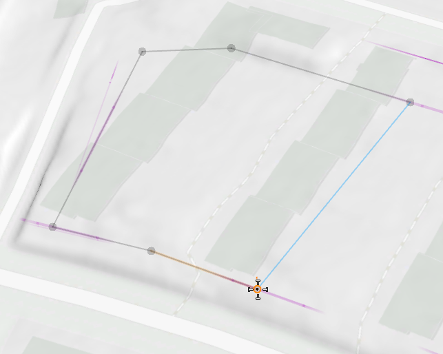
- Navigate to the bottom right of the site and click the Guide Creation tool
 .
. Click the outer edge of the sidewalk and start dragging a guide.

- Turn on the Force Planar toggle button in the tool option.
Now the dashed line is rendered on the same plane as the sidewalk, and an orange plumb line indicates the vertical distance between the position on the drawing plane and the terrain.
Set the Offset option to 7 m and click to create the planar guide.

- Continue to add guides until you're scene looks similar to the following image:

For better visibility you can temporarily hide the terrain in the Visibility settings
 or by pressing F9.
Draw the shapes for the massing
Navigate closer to section A. For this section, you'll draw a shape covering the full available perimeter.
- Select the Polygonal Shape Creation tool
 (S).
(S). Ensure the Force Planar toggle button is turned on so that the height value of the first drawn point is used for all subsequent points ensuring a planar shape. Set the view to top down by pressing Y and uncheck the Wireframe on shaded/textured (7) option in View settings tool
 to temporarily hide the grid.
 - Start at the bottom right corner of the second row of the previous buildings.

- Place the next point at the guide intersection between the existing buildings.

- Trace along the streets and add points at the intersection of the guides.

- Click to place the next point close to the top left street curve.

In force planar mode, all guides are projected onto the current drawing plane.
- Snap to the projected guide and move the mouse along until the plumb line is at the top left corner of the first row of the previous buildings.

- Continue to the top right corner of the second building row and add a point . Finish the polygon by clicking the initial point or by pressing Enter.
- Assign the Perimeter_Stacked.cga rule located in the /ESRI.lib/rules/Components/Massing/Urban_Block folder to the newly created shape and turn on the Wireframe on shaded/textured option.

- In the Inspector window, set Height to 24, Depth to 12, and the Lower_Side_Position to Front-Right-Corner.

- For section B, draw two rectangular shapes to spawn row houses; one starting from the upper guide and the other one from the lower.
- Switch to the Rectangular Shape Creation tool
 (Shift+S) tool.
 Keep the Force Planar toggle button turned on. Use a length of 48 m and depth of 18 m for both rectangles.

- Assign the Rowhouses.cga rule located in the /ESRI.lib/rules/Components/Massing/Suburban_Block/ folder to both shapes.

- Set the Height parameter of the mass model in the upper row to 9 m and the lower one to 12 m in Inspector window.

Place L-Shape mass model
For section C, there is already an existing mass model to put into the scene.
- In the Navigator window, drag the L-Shaped Mass.glb file in the assets folder into the scene.


- Temporarily hide the terrain in the Visibility Settings by pressing F9.
Click the Transform Move tool
 and set the handle position to the bottom outer corner by turning on the Adjust Position and Orientation (o) toggle button.
- Press F9 to turn on the terrain visibility again and use the orange ball to move the L-Shape mass model to the intersection of the lower guide and the previous building location.

- Switch to the Transform Rotate tool
 and drag on the green handle until the L-Shape is aligned with the guide.
- Press F9 to hide the terrain again.

You can see that the bottom part of the building is not perfectly aligned with the guide. The reason for this is that you created the guide from a street which is not flat. You could use the red handle to align vertically too, however for this project the building should be kept flat so you can leave it as is.
- Show the terrain again and click the Transform Move tool .
Turn on the Enable Copy on Move toggle button and drag the orange ball until it snaps to the upper guide.

- Click the Transform Rotate tool to rotate the L-Shape until it is aligned with the guide.

Your scene should now look similar to the following image:

Align massing to the terrain
Now with massing complete, the next step is to align the buildings with the terrain. For each section, you want to apply a different strategy for best results.
- Navigate closer to the perimeter building.
As you can see it integrates quite nicely with the terrain. However, at the street level there should be direct access to the building.

- Click the Terrain Edit Brush tool
 in the main toolbar.
In the tool options set Brush Size to 3.5 m, Smooth Borders to Smooth Range, Range to 2.5 m, and turn on the Easing toggle button. The smoothing range is visualized by a semi-transparent outer ring.
- Hover the pipette (y) over the street to set the terrain height to the level of the street.
Alternatively, you can read the elevation at the pointer position from the information display and enter a fitting value manually.

- Drag along the building without hovering over the street to avoid new overlaps as this street is not perfectly flat.

- Use the Terrain Smooth Brush tool to even out areas between the edited and existing terrain if necessary.

- Repeat the steps above to create the building access area on the upper street.

- Select both row shapes.

- Click the Align Terrain to Shapes tool to open the dialog box.
Set Smooth borders to Constant gradient, Border range to the maximum of 50 m, and Border gradient to 33.33 degrees.

- Click both Apply and Close.

- Flatten the terrain to make the building elevation match the street elevation.
To do this, you can either use the Terrain Edit Brush tool
; or copy the row shape and move it close to the street and apply the Align Terrain to Shapes tool using the previous settings.
- Remove the temporary shape to see the result.

- Repeat the alignment steps for the upper row and smooth other areas where needed.

- Select the upper L-Shape.
- Click the Transform Move tool and drag the green arrow (y axis) until the bottom right corner touches the ground.


- To allow access to the bottom L-Shape from the street, apply the Terrain Edit Brush tool the same way you did when working on the access in section A.

.Note:
Terrain alignment for static models is quite limited because only the pivot point of the model is considered. Align Terrain to Shapes is disabled; and for Align Shapes to Terrain, all translate and project options result in the same position.
Add vegetation
For the next steps, you will add some trees between the buildings. Instead of planting every single tree manually, you will use a CGA rule which randomly distributes trees onto an area. To apply the rule, first draw the shapes covering the area between the buildings.
- Click the Polygonal Shape Creation tool .
In the tool options, make sure to turn off the Force Planar toggle button. For this rule you don’t want the shape to be planar, otherwise the trees will be placed below or above the terrain.
- Draw a polygon similar to the following image:

- Assign the Locate the Plant_Distributor_Simple.cga rule in the rules folder to the shape.
The Plant_Distributor_Simple.cga rule is a modified rule from the Plant_Distributor.cga rule in ESRI.lib with less settings and LowPoly set as the default representation for the trees.


The rule places trees with random type, size, and position based on the random seed value. As soon as you change the seed you will get a different variation.
- To change the random seed click Shapes > Update Seed or press Ctrl+Shift+G in the main menu.
You can customize the result further by adjusting the Density and Distribution attributes in the Inspector window. In the following image, Density is set to 0.2 and Distribution to Border.

- For section B, create another polygon in-between and assign the same rule.
Align the terrain to the shape to avoid having trunks above ground.

- For section A, draw a polygon into the courtyard slightly offset from the building.

That’s it. You can switch between the Existing Conditions and Redevelopment scenarios. Disable the terrain wireframe and hide the Shapes and Graph Networks in the Visibility settings for better visualization of your project.


