The Inspector window  is the main tool for viewing and modifying the attributes and parameters of scene objects, such as shapes, graphs, map layers, or static models. Depending on the type of object selected, the Inspector window
  user interface changes and provides access to the object's properties.
To open the Inspector window  , click Window > Inspector in the main menu, or press Alt+I.
The Inspector window  supports both the editing of properties of a single and a collection of objects. Attributes that are unique across all objects are shown as is. If an attribute has different values in the object collection, the attribute is marked as nonunique with a question mark symbol. Attributes of the lead object are displayed when multiple objects are selected. The lead object is the most recent individually selected object.
For map layers, you to change the map files, modify the bounds, and adjust the display offset (how much the rendering of the map is displaced in relation to the actual map values). In addition, an overlay color and alpha value for the map can be specified. See Map layer overview for more information.
Exploring properties
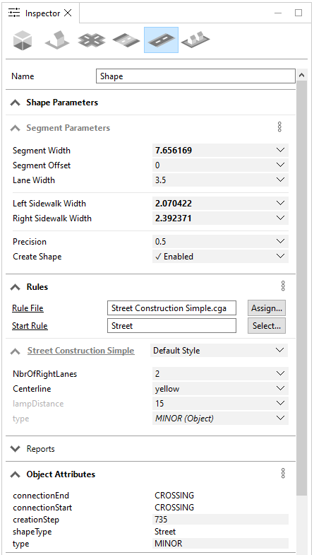
The properties available in the Inspector window  , depend on the types of scene objects selected in the Viewport. You can switch between the different object types by clicking their respective icon. Also, if you hover over the icon, you can see how many objects of that type are selected.
The following image is an example from a selection of different scene objects, in which the segment properties are displayed:
Parameters
Parameters drive the creation of street shapes. You can use the Parameters section to adjust any of the street parameters and change their shape geometry, such as street width or node type.
The following scene objects contain parameters: segments, sidewalk, nodes, and blocks. See Segment and sidewalk parameters, Node parameters, and Block parameters for more information.
Parameters can have different sources that allow fine-tuned control over the values. See Sources for more information.
Note:
Shapes and lots do not have parameters.
Copy and paste parameters
For efficient editing, you can copy and paste the parameters from one selected object to a single or multiple selected objects of the same type. To do this, select an object that uses parameters, such as a node or segment parameter. Next, click More options  and select Copy {parameter type} parameters. Select the objects in which to apply the parameters. Finally, click More options
  and select Paste {parameter type} parameters:

Rules
In the Rules section, you can control CGA rules which may contain attributes, such as color, building style, number of floors, or zoning type.
Rules can be assigned to the following scene objects: shapes, segments, sidewalks, nodes, and lots.
Rule attributes can have sources that allow for precise control of values. See Sources for more information.
Copy and paste rule attributes
You can copy and paste rule attributes to apply to other objects of any shape type in the scene. Follow the same steps as listed in the Parameters section. This time, click More options  in the Rules section to copy and paste the rule attributes:
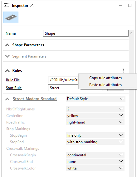
See Rule-based modeling and Work with rules for more information on rules.
Object attributes
Under the Object Attributes section, object attributes are listed that are attached to the selected scene objects.
The following scene objects can have object attributes: shapes, segments, nodes, sidewalks (displays the attributes from a segment or node), blocks, lots, and static models.
Some object attributes are automatically created on import or while generating dynamic shapes. Attribute values which can be edited or deleted have a gray background, while read-only attributes have a white background.
Add an object attribute
To add an object attribute, do the following:
- Click More options
 and select Add new object attribute.
The Create Attribute dialog box appears:

- Provide information for the Attribute Name, Value, and Type.
CityEngine has the following object attribute types:
- BOOL—Boolean
- FLOAT—Floating point value (double precision)
- STR—Character string (UTF-16 encoded)
- BOOL[ ]—Array of Boolean values
- FLOAT[ ]—Array of floating point values
- STR[ ]—Array of character string
Note:
- When providing the value of an attribute, you can provide a NaN value for a float (Not a Number), or a NULL value for a string.
- When providing the value for attributes arrays, separate the values with a comma, such as the following:
- 1,2,3,4,NaN,6
- a,b,c,d,e,f,NULL,h,i,j
- true,false,true,false
- Array values can also be formatted with square brackets for the ease of copying from CGA code or from the console output:
- ["a", "b", "c"]
- [a,b,c]
- Click OK.
Copy and paste object attributes
You can also copy and paste object attributes to apply to other objects in the scene. Follow the same steps as listed in the Parameters section, but instead click More options  in the Object Attributes section of the Inspector window
  to copy and paste the object attributes.
Duplicate and delete object attributes
Object attributes can be duplicated or deleted by right-clicking any object attribute. Read-only attributes can only be duplicated.
Array attributes
CityEngine supports float, string, and Boolean arrays. You can view and edit arrays for both rule and object attributes.
Edit attributes in array table
To create or modify array attributes, do the following:
- Click the Expand menu button
 to expand the array attributes.
Array indices are displayed in gray.
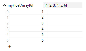
- Click the add button + to add a new row to the end of the array.
The added element is set to the default value for each type (in other words, 0 for floats, "" for strings, false for Boolean).
- Click an element to edit it.
- Right-click to add, duplicate, or delete a row.
2D arrays are displayed in a table view. Row indices are displayed on the left side. Column indices are displayed on top.
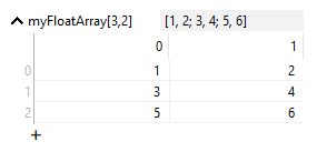
Edit list with array menu
To edit a list with the array menu, do the following:
- Click the Expand menu button
 and select Edit List from the drop-down menu.
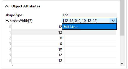
- Modify the values in the Edit List dialog box.
You can replicate the elements, add, duplicate, or delete elements using the toolbar.
You can also right-click to add, duplicate, or delete a row.
- Click OK.
The new values are added to the data model and scene.
Edit table with array menu
When an object has many attribute arrays that follow the prefix_... syntax (for example, MyAttribute_A, MyAttribute_B, MyAttribute_X), you can edit the attribute values from the drop-down menu and select Edit Table for each of the attributes.
To edit the multiple array attributes, do the following:
- Click Edit Table from the drop-down menu of one of the attributes.
This opens a table of array attributes for editing.
- Modify the values in each column.
- Click OK.
Sources
Attributes and parameters can have different sources that allow fine-grained control over the values. The following is a list of possible sources:
Default | The default value used. For rule attributes, this is the initial attribute value. For parameters, this is the algorithm-specific default. |
User | A value that is entered by the user. Whenever the user sets a value (also by Python), uses a slider or handle, the source is set to User defined. |
Object | The value is taken from the corresponding object attribute. The value is displayed in italic and marked with (Object). |
Shape | A rule attribute can use the value from the parent shape. For example, a street shape may sample the street segment's streetWidth. The value is displayed in italic and marked with (Shape). |
Layer | The value is connected to a layer attribute. The value is displayed in italic and marked with the source layer in brackets. See Edit map layer attributes for details. |
Note:
- The most efficient way to create connections and set sources is to use the Connection Editor.
- During rule assignment, object attributes with names that match a rule attribute are connected automatically.
- Whenever you type a value to a parameter or attribute, it will automatically change to user source.
Map attributes with the Connection Editor
Attributes and object parameters in CityEngine can be controlled from various sources. The Connection Editor menu helps to create these attribute connections.
To map the connection of a specific attribute, do the following:
- Click the drop-down menu of the attribute.
- Click Connect Attribute to open the Attribute Connection Editor menu.
- Set the attribute connection.
- Click OK.
In the Attribute Connection Editor menu, you have the following options:
Object Attributes | Connect your attribute to an object attribute. This option is only available if the following occur:
|
Shape Parameters | Connect your attribute to the parent shape parameter. This option is only available if the following occur:
|
Layer Attributes | Connect your attribute to layer attributes from arbitrary layers. Choose the source layer from the drop-down menu, and the desired layer attribute from the drop-down menu. Each layer will provide a list of its available layer attributes, consisting of the following:
Note:If a layer attribute with the same name as your attribute already exists, the new attribute might override the existing one. |
Reset Attributes | You can reset a specific attribute through the Rule default option in the attribute drop-down menu. Depending on the attribute's type, this resets to the default value of the algorithm (for example, Street Shape creation) or to the default value from the rule file (rule attribute). Additional options are available from the attribute context menu (open by right-clicking):
|
Map object attributes with layer attributes
Every layer can have an arbitrary set of layer attributes defined. Whereas, map layers normally use their image data as the source for layer attributes, graph and shape data layers can query their vector objects to layer attributes.
Object attribute mapping and sampling
Layer attributes can be used to map object attributes of their scene objects to attributes with different names or to objects on other layers.
Note:
For simple cases, use the Connection Editor to perform attribute mapping.
Object attributes of nodes, segments, and shapes can be mapped or sampled with layer attributes using one of the following commands:
getFloatObjectAttr(name)
getFloatObjectAttr(name, sample)

getStringObjectAttr(name)
getStringObjectAttr(name, sample)

getBoolObjectAttr(name)
getBoolObjectAttr(name, sample)

getFloatArrayObjectAttr(name)
getFloatArrayObjectAttr(name, sample)

getStringArrayObjectAttr(name)
getStringArrayObjectAttr(name, sample)

getBoolArrayObjectAttr(name)
getBoolArrayObjectAttr(name, sample)
These commands search for object attributes within the layer for a matching name.
If the sample argument is false, only the shape's object attributes are examined. If sample is true (the default value), and the shape has no such object attribute, overlapping shapes in the attribute layer are sampled for the specified name.
If you use the object attribute width on street segments to control the width of created street shapes (the street parameter streetWidth), getFloatObjectAttr allows the attribute layer to obtain the value from other objects.
attr streetWidth = getFloatObjectAttr("width")To use this layer attribute, set the source of the streetWidth parameter in the Street Parameters pane to its own layer. Below is an example with the streetWidth parameter dependent on the attributes:
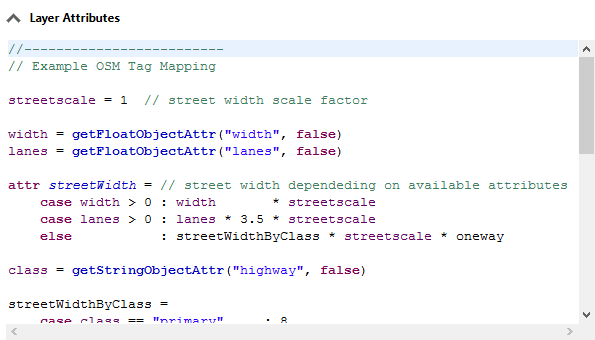
The streetWidth attribute is mapped from object attribute width. The layer attribute streetWidth can now be used to control the street width of street shapes.
Note:
When importing OSM, shape, or GDB data, a predefined set of layer attributes is automatically created on the imported layers. Select the new layers and show or modify the created layer attributes in the Inspector window  .
.
Reports
The Reports section lists all reported variables for selected models. The following table illustrates examples:
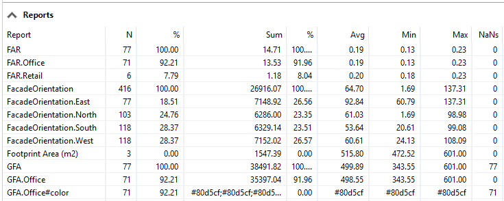
Report | The name of the report variable calculated. |
N | The number of occurrences of the report variable. |
% (N) | The percentage the variable occurs in a group. |
Sum | The sum of variable values. |
% (Sum) | The percentage of the sum of variable values in a group. |
Avg | The average of the variable values. |
Min | The minimum of the variable values. |
Max | The maximum of the variable values. |
NaNs | The number of occurrences with values that are not a number. For example, string variables, such as Retail or Office, don't have numeric values. |
Note:
Report variables may contain a dot that separates a common group name and a variable name, such as FAR.Office or FAR.Retail. The variables are combined in the FAR group.
See Tutorial 11: Reporting for more information. Also, the report operation has further details about reporting with CGA rules.