Available with Network Analyst license.
ArcGIS AllSource provides geoprocessing functionality through the Network Analyst toolbox. These geoprocessing tools, when chained in a model, can help automate repetitive tasks and reduce the probability of error. In a model, the output of one tool is used as input to another tool.
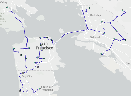
In this tutorial, you will create a model for generating the fastest delivery route connecting 25 stores.
Note:
This tutorial can be completed using as the network data source either the designated tutorial network dataset, ArcGIS Online, or an ArcGIS Enterprise routing service published using a network dataset that covers the geography of the input data of the analysis. If you use ArcGIS Online, credits will be consumed. Learn more about network analysis with a service.Get the data
The data for this tutorial is available for download.
- Go to the data download page.
- Click the Download button, and save the file locally.
- Unzip the downloaded file.
Create a map
To create a map, complete the following steps:
- Start ArcGIS AllSource.
- Create a new project by clicking the Map template. Optionally, change the name of your project and location.
A new project with a map appears.
Add the tutorial data to the project
In this set of steps, you'll add a network dataset to the map.
- In the Catalog pane, which is on the right side of the application by default, right-click Folders and choose Add Folder Connection
 .
.The Add Folder Connection dialog box appears.
- Browse to the folder where you placed the tutorial data, double-click Network Analyst, and click Tutorial to select the folder.
- Click OK.
A connection to the Tutorial folder is created.
- In the Catalog pane, expand Folders > Tutorial > SanFrancisco.gdb > Transportation.
- Drag Streets_ND, which has a network dataset icon
 , onto the map.
 The network dataset is added to the Contents pane and to the map.
- In the Catalog pane, expand Folders > Tutorial > SanFrancisco.gdb > Analysis.
- Drag the Stores feature class onto the map.
The point feature class is added to the Contents pane and to the map.
Next, add one of the network datasets contained in the folder to the map.
Note:
You do not need to add the network dataset to the map if you intend to use ArcGIS Online or an ArcGIS Enterprise routing service as the network data source.
Create and run a model
Follow the steps below in ModelBuilder to create a model and run it.
- On the Analysis tab in the Geoprocessing group, click the ModelBuilder button
 .
.
A new model is opened for editing.
- On the Analysis tab in the Geoprocessing group, click Tools.
The Geoprocessing pane appears.
- Click Toolboxes and expand the Network Analyst Tools toolbox.
- Click the Analysis toolset and drag the Make Route Analysis Layer tool into the new model window.
- Double-click Network Data Source in the model window.
- From the Network Data Source drop-down list, select Streets_ND and click OK.
- Double-click the Make Route Analysis Layer tool in the model.
The Make Route Analysis Layer tool dialog box appears so you can edit the parameters.
- Change the Sequence parameter to Find best order and click OK to close the tool dialog box.
The Find best order option allows the order of the route stops to be rearranged to minimize the overall travel time.

- In the Geoprocessing pane, from the Analysis toolset in the Network Analyst Tools toolbox, drag the Add Locations tool into the model window.
- Select the Stores feature layer in the Contents pane and drag it into the model window to the left of Add Locations.
- Connect Stores to Add Locations and click Input Locations on the context menu that appears.
- Connect Route to Add Locations and click Input Network Analysis Layer on the context menu that appears.
- Click the ModelBuilder tab on the ribbon.
- In the View group, click the Auto Layout button
 .
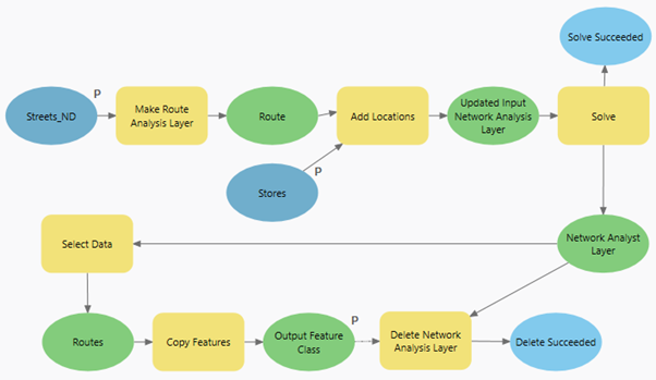
.The model is arranged in a logical order and resembles the example below:

- In the Geoprocessing pane, from the Analysis toolset in the Network Analyst Tools toolbox, drag the Solve tool into the model window.
- Connect the output Updated Input Network Analysis Layer to Solve. Click Input Network Analysis Layer on the context menu that appears.
- On the ModelBuilder ribbon, from the Insert section, click the Utilities drop-down menu and choose the Select Data option.
- Connect Network Analyst Layer to Select Data. Click Input Data Element on the context menu that appears.
- Open Select Data and from the Child Data Element drop-down menu, select the Routes sublayer.
- Click OK.
- In the Geoprocessing pane, in the search bar, type Copy Features and drag the Copy Features (Data Management) tool into the model window.
- Connect Routes to Copy Features and click Input Features on the context menu that appears.
This will copy the extracted features from the Routes sublayer to a new feature class in your project geodatabase.
- In the Geoprocessing pane, open the Network Analyst Tools toolbox and from the Analysis toolset, drag the Delete Network Analysis Layer tool into the model window.
The Delete Network Analysis Layer tool is valuable in models where a network analysis layer is created as an intermediate step. If such a model is run repeatedly, unwanted sublayer data may accumulate in the project geodatabase. This tool cleans up the network analysis layer's analysis data in the model workflow.
- Connect Output Feature Class to Delete Network Analysis Layer and click Precondition on the context menu that appears.
This ensures that the network analysis layer is not deleted until the routes are copied to a new feature class.
- Connect Network Analyst Layer to Delete Network Analysis Layer and click Input Network Analysis Layer on the context menu that appears.
- Click the Auto Layout button
 to arrange the model elements.
Note:
The layout of the model elements has been modified from the default to make it easier to see in the image.
- Click the Save button
 to save the model.
 - Click the Validate button
 to ensure that all the elements of the model are valid.
 - Click the Run button
 .
. - When completed, close the status window .
- In the Catalog pane, expand Databases and look for the Routes_CopyFeatures feature class in the project geodatabase.
- Add the Routes_CopyFeatures to the current map to visualize the output.

- Turn off the layer visibility and proceed to the next section.

Note:
The Network Data Source input variable may not be present. In that case, right-click the Make Route Analysis Layer tool and choose Create Variable > From Parameter > Network Data Source. The items in the model will still appear gray because the Network Data Source variable has not yet been set to a value, but you can proceed with the tutorial steps.

Note:
You can also specify ArcGIS Online or ArcGIS Enterprise portal as the network data source or use a catalog path to a network dataset.
Note:
You can also use a web feature layer hosted in an ArcGIS Online or ArcGIS Enterprise portal to load your input features.
Once the model is successfully run, optionally, you can visualize the output of this model which here, is a line feature class that stores the route through the input locations.
Run the model as a geoprocessing tool
As with other geoprocessing tools, you can open and run a model tool in the Geoprocessing pane. Variables that are set as model parameters show as tool parameters when the model is run as a geoprocessing tool, allowing you to specify different data or values for your model to process than what was specified when the model was created.
- Switch to the model view and right-click Stores. Select Parameter from the context menu that appears.
The variable is set as a parameter, which is indicated by the letter P next to the variable in the model. The user of the model tool will be able to choose the input for the model.
- Repeat step 1 for the Streets_ND and Output Feature Class variables in the model.
Setting Streets_ND as a model parameter allows the user of the model tool to choose the network data source to use for the analysis. Since Output Feature Class is the final output of the model, setting it as a parameter allows the model tool user to specify their desired output file path. Additionally, the output will be added to the map view and the Contents pane when the tool is run.

Note:
The layout of the model elements has been modified from the default to make it easier to see in the image.
- Save and close the model.
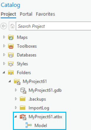
The model is saved as a geoprocessing tool in a toolbox.

- Browse to the location where the model is saved and double-click it, or right-click it and choose Open.
The model appears in the Geoprocessing pane.
- Populate the parameters, if necessary, and click the Run button
 at the lower right to run the analysis.
A new feature layer showing the calculated optimal route is added to the map view and the Contents pane.