Modify default symbols and color ramps
In this topic
Esri Maps for MicroStrategy provides a default set of symbols, colors, and color ramps used to style features on the map. These are defined in two JSON configuration files: one that specifies the default symbols in user mode (for report consumers), and one that defines them in design mode (for report authors).
Administrators can edit these files to modify the default symbols and color ramps available to report designers and viewers.
Note:
It is recommended that you create a backup of your default symbols definition files before you modify the properties.
The symbols definition files define default values for the following:
- Fill symbols
- Line symbols
- Heat map color ramps
- Marker symbols
- Class break color ramps
- Unique value color ramps
Edit the default symbols definition
Modify the four default symbols definition files to make changes to the default symbols available to report consumers and authors.
Note:
These changes must be made on all web servers on which the MicroStrategy plug-in has been installed (web and mobile web servers).
- Locate the default symbols definition file.
Browse to <MicroStrategy_plugin_directory>\javascript\configuration\design\symbols.json.txt.
- Create a backup copy of the original symbols.json.txt file—for example, backup_symbols.json.txt.
- Using your preferred text editor, open symbols.json.txt.
The following code shows an example of a default symbols definition file that describes the default symbology used in your application. Each of these is an array of JSON objects that describe the default symbols used to style different types of features on the map. Objects are enclosed in curly brackets ({ }) and separated by commas. Multiple objects are enclosed in square brackets ([ ]) to indicate an array. Each JSON object contains properties formatted as name-value pairs that represent data.
{ defaultFillSymbols: [], defaultLineSymbols: [], defaultMarkerSymbols: [], heatMapColorRamps: [], classBreaksColorRamps: [], uniqueValueColorRamps: [] } - Modify the default symbols and color ramps as desired, following the conventions described in the following sections.
- Validate the updated JSON code using a validation tool such as JSONLint.
- Save and close the file.
- Test your application in Report mode.
- Locate the report, document, and mobile symbols definition files for other MicroStrategy modes.
These are located in the following directories:
- <MicroStrategy_plugin_directory>\javascript\configuration\report
- <MicroStrategy_plugin_directory>\javascript\configuration\document
- <MicroStrategy_plugin_directory>\javascript\configuration\mobile
- Repeat steps 2 through 6.
- Test your application in other MicroStrategy modes.
Fill symbols
Simple fill symbols define the default styles applied to polygons. Each fill symbol object is defined as follows:"defaultFillSymbols": [{
"color": [17, 140, 17, 179],
"type": "esriSFS",
"style": "esriSFSSolid",
"outline": {
"type": "esriSLS",
"style": "esriSLSSolid",
"color": [17, 140, 17, 179],
"width": 1.25
}
},
...
],
- color—Specifies the four-element array that defines the red, green, blue, and alpha values for the line, in that order. Values range from 0 through 255.
Note:
The fill color applies only when the style property is set to a solid fill (esriSFSSolid); if you specify a pattern fill, the color property is ignored.
- type—Specifies the type of symbol. The type property for a simple fill symbol is esriSFS.
- style—Specifies the style applied to the fill. The default fill style is esriSFSSolid. Available fill patterns include the following:
- esriSFSSolid
- esriSFSCross
- esriSFSDiagonalCross
- esriSFSBackwardDiagonal
- esriSFSForwardDiagonal
- esriSFSHorizontal
- esriSFSVertical
- esriSFSNull (invisible)
- outline—Specifies the properties of the polygon outline. For details, see Line symbols.
The following image illustrates the default fill symbols:
 |  |  |  |  |  |  |
esriSFSSolid | esriSFSCross | esriSFSDiagonalCross | esriSFSBackwardDiagonal | esriSFSForwardDiagonal | esriSFSHorizontal | esriSFSVertical |
Line symbols
Simple line symbols specify the default styling applied to polylines or polygon outlines. Each line symbol object is defined as follows:],
"defaultLineSymbols": [{
"color": [255, 11, 11, 255],
"width": 0.4,
"type": "esriSLS",
"style": "esriSLSSolid"
},
...
]
- color—Specifies the four-element array that defines the red, green, blue, and alpha values for the line, in that order. Values range from 0 through 255.
- width—Specifies the width of the line, in points.
- type—Specifies the type of symbol. The type property for a simple line symbol is esriSLS.
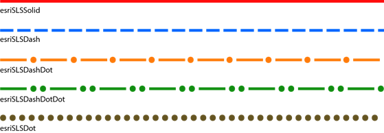
- style—Specifies the style applied to the line. The default line style is esriSLSSolid. Available line patterns include the following:
- esriSLSSolid
- esriSLSDash
- esriSLSDashDot
- esriSLSDashDotDot
- esriSLSDot
- esriSLSNull (invisible)
The following image illustrates the default line symbols:
Marker symbols
Marker symbols are used to style point features. The default marker set defines the symbols that are automatically used to represent features when point data is added to the map.
By default, Esri Maps for MicroStrategy uses simple marker symbol shapes to symbolize point data added to the map.
The defaultMarkerSymbols section of the default symbols definition file (symbols.json.txt) points to the symbols that should be used by default to symbolize points on the map. You can modify this section to point to different symbols included with Esri Maps for MicroStrategy. Each marker symbol object is defined as follows:],
"defaultMarkerSymbols":[{
"angle": 0,
"xoffset": 0,
"yoffset": 0,
"type": "esriSMS",
"style": "esriSMSCircle",
"color": [255, 11, 11, 128],
"size": 7.25,
"outline": {
"color":[255,11, 11, 255],
"width": 1,
"type": "esriSLS",
"style": "esriSLSSolid"
}
},
...
]
- type—Specifies the type of symbol. The type property for a simple marker symbol is esriSMS. For a picture marker symbol, the type is esriPMS.
- style—Specifies the style applied to the symbol. The default symbol style is esriSMSCircle. Available symbol styles include the following:
- esriSMSCircle
- esriSMSCross
- esriSMSDiamond
- esriSMSSquare
- esriSMSX
- color—Specifies the four-element array that defines the red, green, blue, and alpha values for the symbol, in that order. Values range from 0 through 255.
- size—Specifies the size of the symbol, in points.
Optional properties include the following:
- angle—Specifies the number of degrees (0 to 360) by which a marker symbol is rotated. Rotation occurs from east in a counterclockwise direction, where east is the 0° axis.
- xoffset—Specifies the horizontal offset, in points, of the marker symbol from the actual point location. Positive values offset to the right; negative values offset to the left.
- yoffset—Specifies the vertical offset, in points, of the marker symbol from the actual point location. Positive values offset upward; negative values offset downward.
- outline—Specifies the properties of the symbol outline. For details, see Line symbols.
The order in which the marker symbol objects are defined in the file corresponds to the order in which they are used to render features on the map as new point data is added. For example, by default, red circle shapes (esriSMSCircle) are used for the first point layer, blue circle shapes for the second layer, and so on.
Heat map color ramps
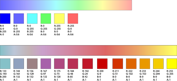
Color ramps for heat maps specify a range of colors applied to a group of symbols that represent a heat map. Each color ramp is specified as a set of colors defined as red, green, blue, and alpha values.
For example, the following JSON objects specify the colors that make up the color ramps shown below:],
"heatMapColorRamps": [
[
[0, 0, 255, 0],
[0, 0, 255, 0.6],
[0, 255, 255, 0.6],
[0, 255, 0, 0.6],
[255, 255, 0, 0.6],
[255, 0, 0, 0.6]
],
[
[133, 193, 200, 1],
[144, 161, 190, 1],
[156, 129, 132, 1],
[167, 97, 170, 1],
[175, 73, 128, 1],
[184, 48, 85, 1],
[192, 24, 42, 1],
[200, 0, 0, 1],
[211, 51, 0, 1],
[222, 102, 0, 1],
[233, 153, 0, 1],
[244, 204, 0, 1],
[255, 255, 0, 1]
]
]

Class break color ramps
Color ramps for class breaks specify a range of colors applied to features grouped into classes. The start, end, and intermediate colors that make up the color ramp are defined as objects that define the red, green, and blue values of each color (colors may also be described using hex values or named color values).
For example, the following JSON objects specify the colors that make up the color ramps shown below:],
"classBreaksColorRamps": [
{ "0.0": [124, 4, 4], "1.0": [247, 198, 198] },
{ "0.0": [2, 32, 227], "0.5": [0, 242, 242], "1.0": [32, 204, 16] },
{ "0.0": "#feeedf", "0.25": "#fdbe86", "0.5": "#fd8c3d", "0.75": "#e65507", "1.0": "#a63700" }
]
Unique value color ramps
Unique value color ramps specify a range of colors applied to features grouped according to unique values. The start, end, and intermediate colors that make up the color ramp are defined as objects that define the red, green, and blue values of each color (colors may also be described using hex values or named color values).
For example, the following JSON objects specify the colors that make up the color ramps shown below:],
"uniqueValueColorRamps": [
{ "0.0": [51, 153, 51], "0.5": [255, 255, 191], "1.0": [255, 0, 0] },
{ "0.0": [161, 215, 106], "0.5": [247, 247, 247], "1.0": [233, 163, 201] },
{ "0.0": [123, 50, 148], "0.5": [247, 247, 247], "1.0": [0, 136, 55] }
]
Test the modified default symbols and color ramps
Verify that your custom picture markers are available to Esri Maps for MicroStrategy report designers and viewers.
Note:
These changes must be made on all web servers on which the MicroStrategy plug-in has been installed (web and mobile web servers). To avoid confusion, copy the modified symbols.json.txt file to all mode directories for all installations.
- Save and close symbols.json.txt.
- Restart your web application server and clear your browser cache.
- In MicroStrategy Web, create a blank document and add the Esri Maps for MicroStrategy widget to the document. View the widget properties to view and configure the map.
- Add point, line, and polygon data to the map. If you modified any of the color ramps, verify that these are applied as expected after grouping the data or applying a heat map.
Esri Maps for MicroStrategy now uses the modified default symbols and color maps to style the data.
- Save and close the map.
- Preview the report to ensure that the modified default symbols and ramps are used in all other MicroStrategy modes.