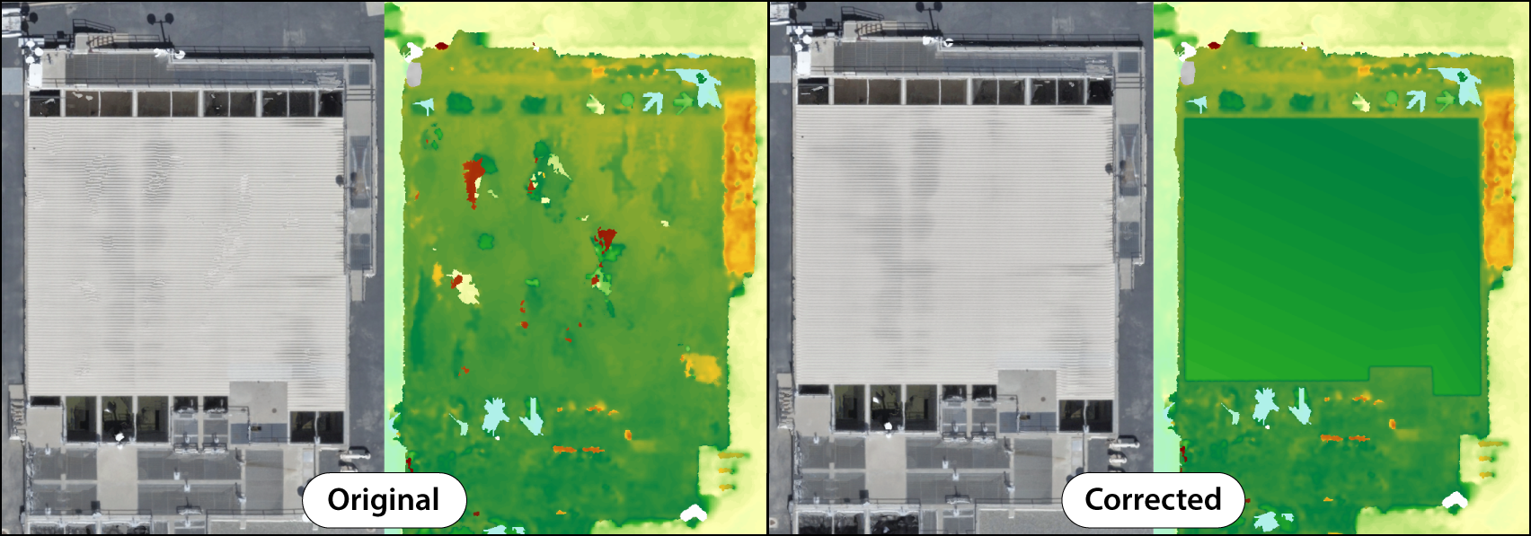
In ArcGIS Drone2Map, the point clouds created from project imagery are used to generate 2D and 3D products such as elevation surfaces, True Orthos and 3D Meshes. Since the point cloud is a key component of this process, any abnormalities in it can lower product reconstruction quality. Shadows, clouds, or lack of image coverage can cause areas of uncertainty in the point cloud features to have too many or too few points and become distorted.
You can create correction features for these areas of poor reconstruction to be used during preprocessing to improve product results. The point cloud will be resampled within the bounds of the correction feature to a higher detail by restricting points within the correction feature area to only use the immediate neighboring points during processing. This typically results in cleaner edges to buildings and features with smoother surfaces.
Correction features require exact z-values to work properly. There are two types of geometry that can be used when drawing correction features 2D and 3D. When drawn with 2D geometry, correction features will use the digital surface model created from the block adjustment step to obtain their z-value (height). 3D geometry correction features are drawn as a multipatch and will typically use the mesh product for z-values, but may use the DEM if the vertex is placed in a spot where the mesh did not generate such as underneath a roof overhang.
2D correction features
Correction features that are drawn with 2D geometry apply to the True Ortho and DSM products. They are best used when attempting to correct objects that are difficult to reconstruct, such as vegetated areas or complex materials. They can also be used to potentially close up any possible voids within a resulting product. If there are still issues with default settings, then configuring a project to the Ultra point cloud density setting will also generate a mesh that is used to correct the products during reprocessing.
One example of 2D correction features, would be if you were to draw a correction feature over a flat roof. The area within the correction feature polygon would be smoothed out to achieve a more uniform surface.

3D correction features
Correction features are drawn with 3D geometry and can be used to correct vertical areas within meshes. They work similarly to 2D corrections by flattening and filling in the area so that the mesh is conformed to match the drawn feature. They are most commonly used on objects that tend to be highly reflective or transparent like glass facades and roofs, as well as surfaces that lack distinct textures.
One example of using 3D correction features, would be correcting voids that appear within a 3D mesh. The area within the vertically drawn correction feature is void filled and smoothed out with the mesh texture then aligning with the new geometry.

Create correction features
Create correction features to be applied to products before or after processing.
Use the Create Correction Feature tool to manually add a correction feature to the project.
- On the Home tab, in the Pre-processing group, click the Correction Feature drop-down menu
- Use the Geometry Type option to define if the correction is intended for 2D or 3D products.
Note:
Any existing correction features need to be cleared before changing geometry type. - Select the Create Correction Feature option.
The Create Correction Feature pane appears and the map changes to either the 2D or 3D Map depending on the geometry type used.
- Click the Correction Feature template and draw new polygons over areas to be corrected.
Note:
Each vertex in a correction feature must have its z-value set at the correct height so that it fits the actual shape of the object (such as creating two sloped rectangles for a roof) to obtain the best results. Z-values are automatically populated when drawing features. However, if correction features are not processing properly the z-values for vertices can be adjusted manually. For steps regarding this process, see Specify an elevation for 3D features.
- Finish and save the polygons you created.
- Click the Home tab, and in the Processing group, click the Start button to being processing.
The drawn correction features are applied to the point cloud during processing, and the points within the correction area are sampled to the highest density.
Import a correction feature
Import a correction feature to be applied to products before or after processing.
- On the Home tab, in the Pre-processing group, click the Correction Feature drop-down menu and select Import Correction Feature.
The Browse to Feature Class window appears.
Note:
When using 2D geometry you can import polygon feature classes, for 3D geometry you can import multipatch feature classes.
- Browse to the correction feature layer on your file system, select the layer, and click OK.
The features are imported into the Correction Feature layer in the Pre-Processing group in the Contents pane.
Remove correction features
To remove correction features that were drawn or imported into the project, on the Home tab, in the Pre-processing group, click the Correction Feature drop-down menu and select Remove Correction Feature.
All correction features are removed from the Correction Feature project layer.
Use correction features with tile-based processing
You can use correction features in combination with tile-based processing to fix areas of poor reconstruction. There are two methods of applying the tile-based processing workflow: merged and unmerged. Using merged tiles will reprocess tiles and overwrite the product leaving a single output file while also saving storage space. Using unmerged tiles will output the individual tiles into the project folder and allows you to see which specific tiles were updated. To learn more, see Tile based processing.
Note:
Tile-based processing is only supported on the True Ortho, DSM and Point Cloud products.
To see tiles within the product folder, the Delete Tiles processing option needs to be unchecked.