To access the tutorials in ArcGIS CityEngine, click Help > Download Tutorials and Examples. After choosing a tutorial or example, the project is automatically downloaded and added to your workspace.
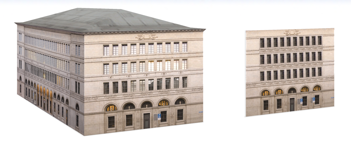
The Facade Wizard allows you to create complex CGA facade rule templates. The tool doesn't require you to write CGA code; instead, the code is automatically produced in the background by CityEngine. The wizard allows complex structures to be generated quickly and efficiently. With this tool, you can create CGA rules that can adapt to any facade geometry.
The following images are a photograph of an example facade and the resulting models after the rule file has been assigned to different-sized building facades. Note that the number of windows adapts to the facade size. With the Facade Wizard, you can create large collections of facade templates for reuse, which may be helpful in upcoming projects.
The Facade Wizard tutorial is split into two separate tutorials: Tutorial 13a: Facade Wizard—Basic facade creation and Tutorial 13b: Facade Wizard—Advanced facade creation. In this tutorial, you will create a basic façade by loading an image file into the Facade Wizard to create a facade rule template with single and repetitive splits.
Get started with the wizard
- Expand the Tutorial 13A_Facade_Wizard_Basic_Facade_Creation tutorial folder in the Navigator window.
- Double-click the FacadeWizard_1_SNB.cej file in the scenes folder to open the scene in the Viewport window.
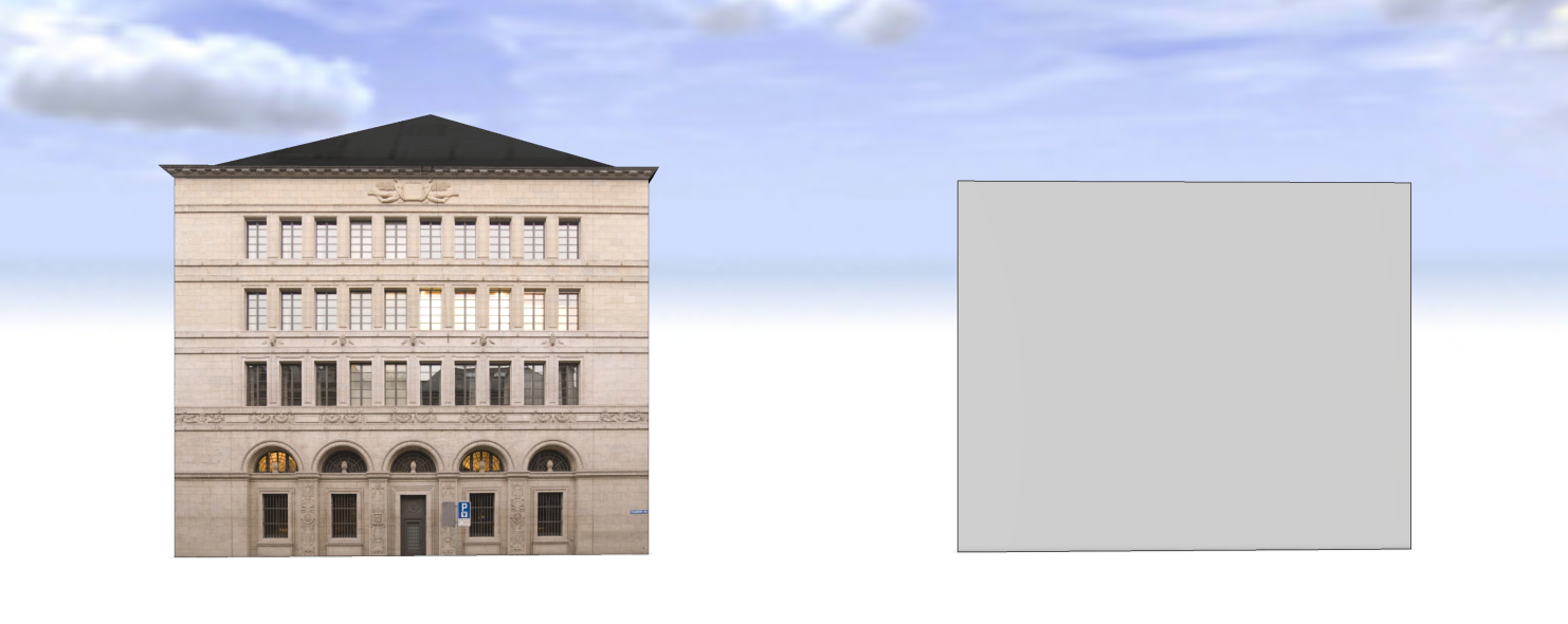
The starting scene appears with a textured OBJ model next to a vertical 2D rectangle with no texture. This view is also bookmarked as the Starting Location. If you navigate away from this view navigate back by clicking on this entry in the bookmarks menu, or press Numpad_0.
- Click Window > Facade Wizard > to open the Facade Wizard window.
The Facade Wizard is an interactive tool for procedural texturing that allows you to parse an image into repeatable facade components and then articulate different levels of detail resulting as a CGA rule. That rule can then be assigned to 2D shapes representing building facades for scalable 3D textures.
Use this tool to create accurate interpretations of existing conditions, to integrate complementary models of small architectural details into a 3D facade or to apply custom textures as inspiration for new building envelopes.
- In the Facade Wizard window, click the New Facade from Image tool
 and navigate to the tutorial assets folder. Open the SNB_ShortFacade.jpg file.
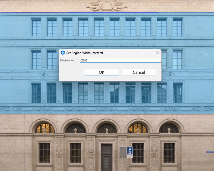
 - The region width will dictate the scaling of the facade. To match the window and door splits of an existing building facade, measure the width of one side and use that measurement as the region width. For the Swiss National Bank's short facade, input 26 meters.
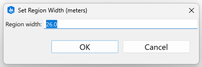
- Click OK.
- Next, in the Facade Wizard, right-click to set the region height at 19.4 meters.
Note:
The Set Region Width allows you to enter the total width of the facade so that the split dimensions make geometric sense. This value cannot be reset later.
- At this stage, it is helpful to adjust the CityEngine layout to make the Facade Wizard your main view. To set this up:
- Click and drag the Facade Wizard window until you see the window inset guides.
- When the window snaps to your preferred position, release the mouse button. This creates a split screen of the Viewport window and the Facade Wizard window.
- Resize as needed.
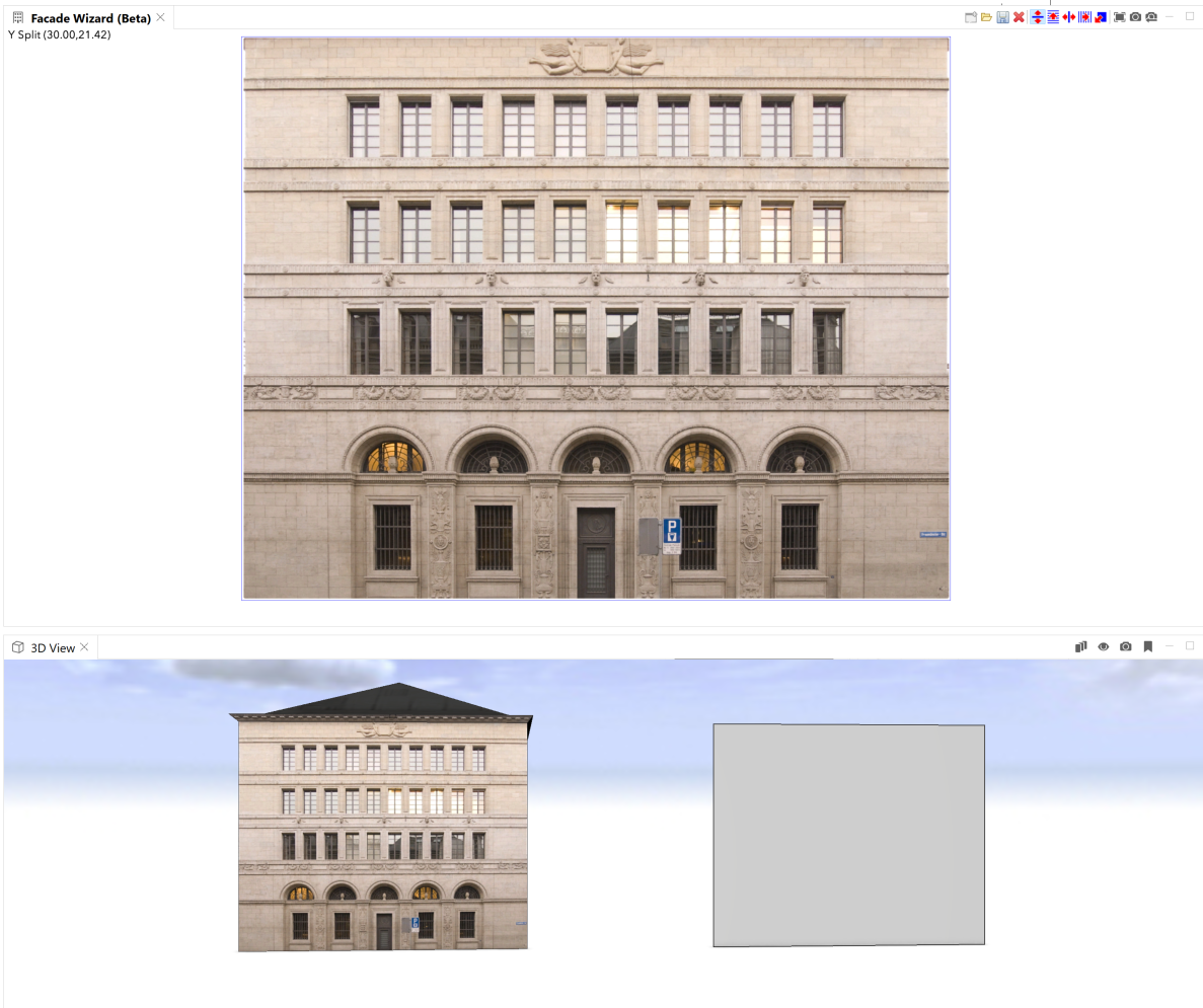
Understanding Splits
The split tools in the Facade Wizard subdivide any selected facade photo/image along a specified scope axis (x, y) within an area (region). Each split is ultimately represented as a split operation in a resulting CGA rule to subdivide the facade shapes.
Those shapes can then become procedurally generated windows, doors, cornices, and decorative components depending on the desired level of detail (LOD). Splits done this way also align the appropriate textures to the subdivided shapes and allows for proportionate scaling when the CGA rule gets assigned to differently sized building facades.
Ground floor splits
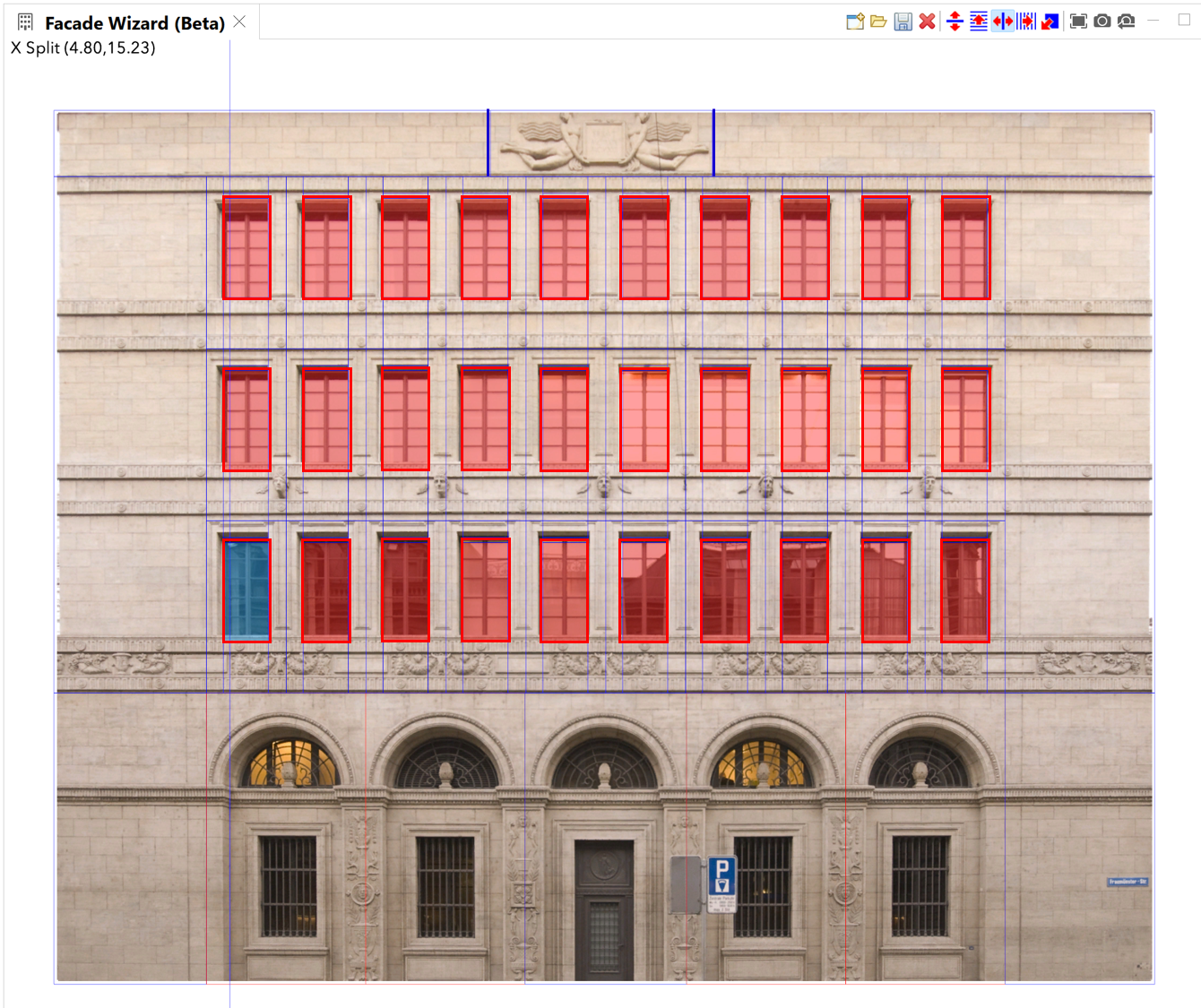
In this section, you will activate the Facade Wizard split tools determined by which axis/direction you can cut along. It is best to set splits along the edges of facade components as shown in the facade image while considering which subdivided regions will be repetitive. After choosing which type of split is needed, you can hover over the image in the tool interface to see red and blue line indicators showing where the split may be applied. Use the same tumble, rotate and pan navigation as you would in the Viewport window.
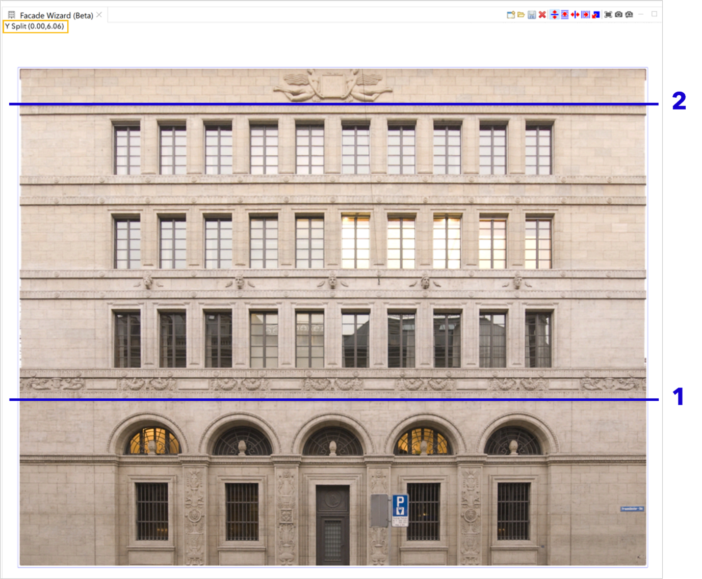
- 1. Verify that the Y Split tool
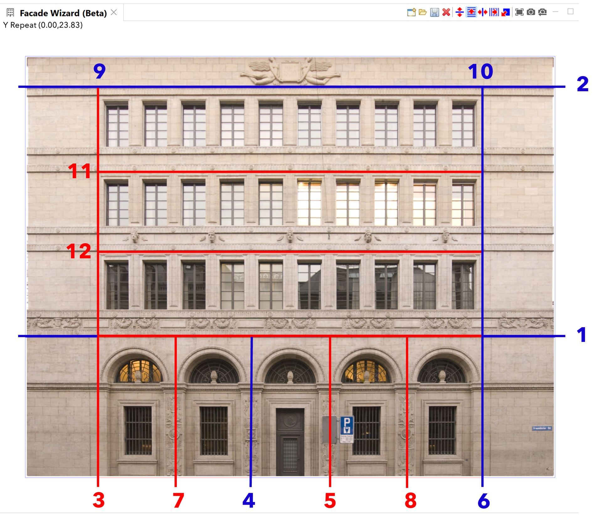
 is selected and create horizontal splits 1 and 2 to block the main building masses as ground floor, upper floors, and roof.
- Select the region between splits 1 and 2 and right-click to edit the region width. Update the default 30 to read 26.0 meters.
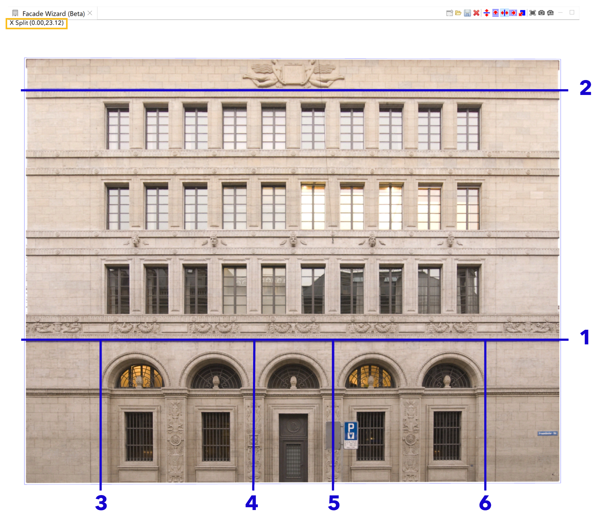
- Next, break up the ground floor to include the two most left windows, the entrance, and two right windows.
- Click the X Split tool
 .
. - With the X Split blue line, hover over the ground floor split area and click the left side on the ground floor to create splits 3 and 4 to separate the two (repetitive) left windows.
- Continue to create vertical splits and click the right side of the entry to create split 5.
- Finally, click the ground floor at the far right to create split 6 and define the two (repetitive) right windows.
Tip:
To select the correct split type faster, you can also cycle through them by using the left and right arrow keys.
Note:
After splits have been set, you can go back to the split line, click and drag to edit the split position interactively.
- Click the X Split tool
- Click the X Repeat tool
 to change the split type to repetitive splits.
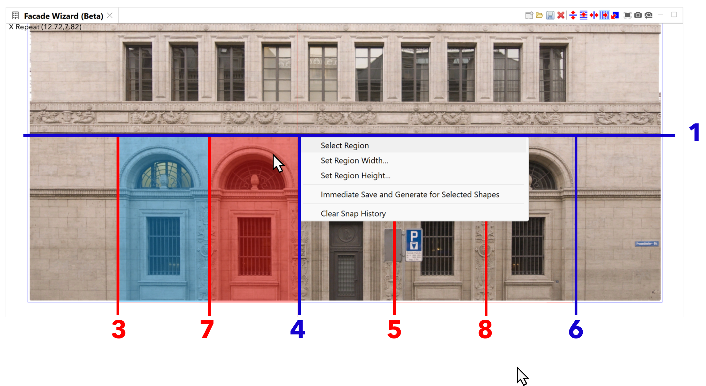
- Create the red repetitive splits 7 and 8.
- The line representing split 3 has now become red to represent the new repetitive split.
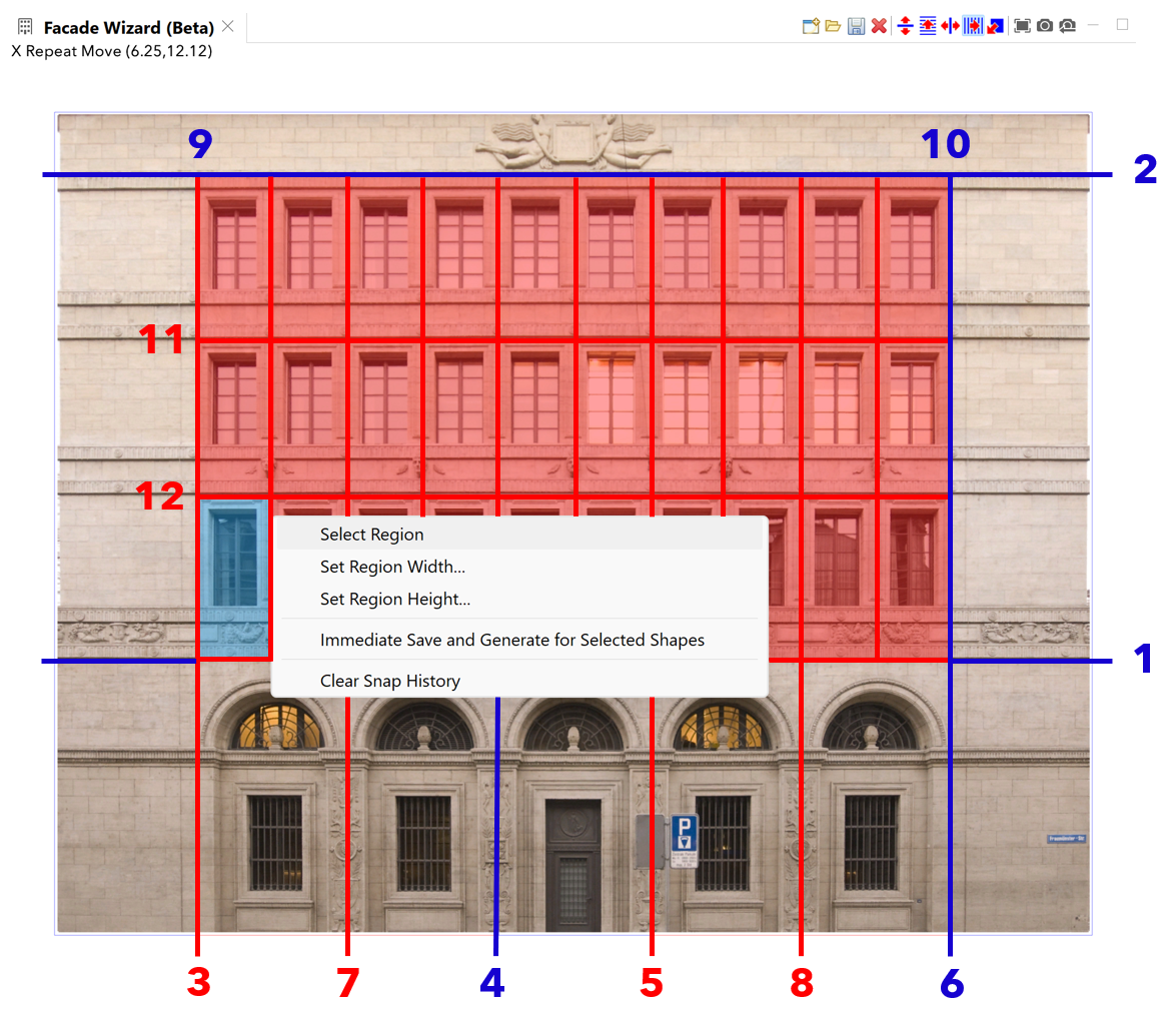
- On the left ground floor window split area where the light does not shine through, right-click and choose Select region. With this step you have chosen which part is used for the texturing of repetitive splits. In this case, you will repeat the region with the light off in the background. Repeat the same steps for the right (repetitive) windows.
Upper floor splits
- For the upper floors, to create splits 9 and 10, click the X Split tool
 and press Shift to snap to splits 3 and 6, which were created on the ground floor level.
 - Enable the Y Repeat tool
 and hover to set up the position of the splits and click one time inside the upper floors area.
 - Now right-click to select the upper regions to ensure that the two remaining horizontal repetitive splits, 11 and 12 are set up.
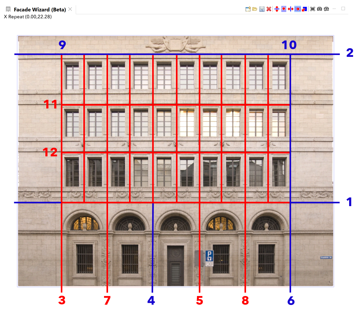
- 4. Click the X Repeat tool
 and click once to create the 9 vertical repetitive splits resulting in 3 rows of 10 window sections.
- Select one of the darker upper windows and set the repetitive region by choosing Select Region.
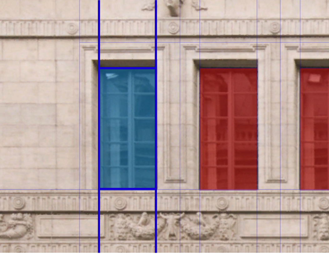
- Use the X Split and Y Split tools to isolate the glass section of the upper floor windowpanes.
- On the roof, use the X Split tool
 to create vertical splits on either side of the roof ledge ornament.
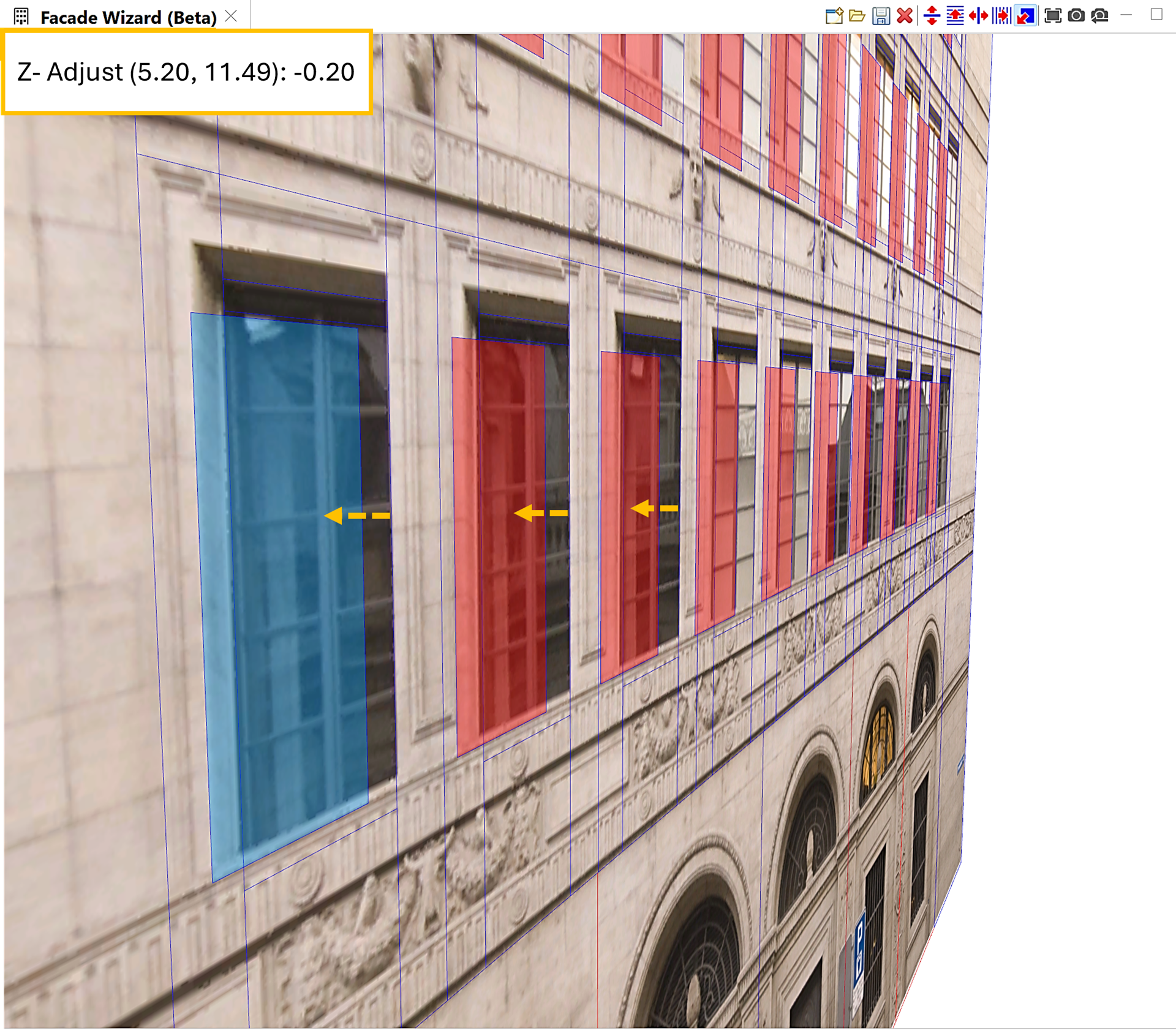
- To add a more volumetric appearance to the currently flat surface, you can define an offset by setting the Z Adjust value per split tile. Click the isolated window region and slide it back to create an indented window ledge. Notice the Z Adjust value changes in the upper left corner of the Facade Wizard window. Do this on as many parts of the building as you want.
Tip:
The CityEngine 3D View navigation works the same in the Facade Wizard. This helps to zoom and pivot interactively while detailing your facades. 3D navigation is particularly useful when using the Z Adjust feature. To tumble or rotate your view, press Alt and click to drag in the active Facade Wizard window to view the Z adjust edits from a side angle.
- Click the Save Rules and Textures for Current Facade tool
 and name it gen_Facade_SNB.cga to generate a rule file for the facade. Do not close the Facade Wizard window
Note:
Split edits can only be saved in the active work session of the facade editing. You cannot import a saved CGA file and edit visually in the facade wizard after edits are saved and the window has been closed.
- Find the new facade rule in the rules folder
- Click and drag the CGA rule onto the shape in the Viewport window to assign it. Select the shape and click Generate Models tool
 (Ctrl+G) it to see the volumetric facade.
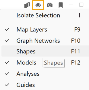
 - At the top of the Viewport window, click the Visibility Settings tool
 and uncheck Shapes to hide the original shape.
Note:
To see the volumetric facade correctly, hide the shapes by unchecking Shapes (F11) in the Visibility Settings tool
 . When you want to select other facades and repeat these steps, you must activate it again.
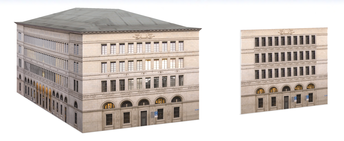
- You have now created a scalable facade based on the original model. Notice the similarities and differences between them. To see the finished result including an example of this facade scaled up to a bigger facade shape, open the FacadeWizard_2_SNB.cej scene.
Continue on with Tutorial 13b: Facade Wizard—Advanced facade creation to learn more advanced facade creation workflows, such as creating a rule template and inserting assets in the facade.