CityEngine features the Facade Wizard, a streamlined interactive tool for the rapid creation of textured 3D facades. The tool outputs CGA code that can be used within CityEngine as any other piece of CGA code. This document provides an overview of the typical facade creation workflow and explains the individual steps. You can open the Facade Wizard by selecting Window > Facade Wizard in the main menu.
See Tutorial 13: Facade wizard for more in-depth information.
Basic workflow
The basic workflow of the Facade Wizard is as follows:
- Open the Facade Wizard.
- Select a shape or a single face of a multiple-face shape in your scene. Alternatively, select a facade texture image in your project using the Navigator.
- Load the selected shape or image into the Facade Wizard by clicking the New Facade button in the Facade Wizard toolbar.
- Click the New Facade from Image to load an image from the file browser.
- Use the standard CityEngine 3D navigation controls and shortcuts to navigate when editing the facade (in particular, press A to frame the whole facade, and press Z to position the camera in front).
- Add vertical and horizontal splits by clicking the Y Split and X Split options, respectively.
- Add vertical and horizontal repeats by clicking the Y Repeat and X Repeat options, respectively.
- Move the mouse over the facade or individual regions. Lines indicate where the split or repeats will be added.
Tip:
Use the left and right arrow keys switch between the different tools.
- Move existing splits or modify repeats by moving the mouse near the split or repeat you want to edit.
- Drag the mouse to move or adjust the splits or repeats.
- Adjust the depth of the final regions by using the Z-adjust tool.
- Save the facade by clicking Save option .
A file browser will ask you to specify a CGA rule file where the rules will be written. If your facade was loaded from a shape, the shape's or face's rule file and the start rule will be set, and you can select and generate the model.
Note:
Currently, the Facade Wizard creates CGA code "one way" only, i.e., you cannot "load" a facade with associated rules. However, the created CGA code can easily be edited using the CGA Editor.
Additional considerations
Flexible vs. rigid splits | Normally, if you have multiple splits along an axis (X or Y), the Facade Wizard will assign flexible splits automatically, so a created facade can adapt to different shapes. However, in some cases, it is necessary to manually define split types. Move with the mouse over a region and press the up or down arrow keys to change the split model: A bold yellow line indicates a rigid split, a dotted yellow line indicates a flexible split. No line indicates automatic mode. |
Facade dimensions | When loading images, a dialog will ask for an approximate initial width. When loading a shape, the dimensions will be taken from the actual shape size. Note:A more precise width or height can be specified at any time using the context menu's "Set Region Width / Height..." entry. |
Select region | Using the context menu's "Select Region" you can specify which texture area will be used for repeats. The selected region appears differently colored than the other repeating regions. |
Snapping | The Facade Wizard maintains a history of all previous X and Y splits. Press Shift when adding splits, and the split will snap to previous locations. The snapping history is kept when loading new facades, making snapping very useful when for instance creating multiple facades of the same mass volume. Use the context menu to clear the snap history. |
Crop Image Tool
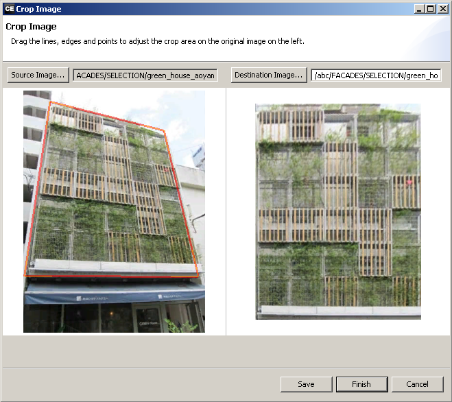
The Crop Image Tool provides an intuitive and effective means for the preparation of facade textures; perspective correction and region selection are done in one step. Starting with automatically detected facade bounds, select the facade or an element of interest. You adjusted visually while watching the result in real time. To open the tool, select the file and click Shapes > Crop Image... from the main menu or Crop Image... from the context menu of an image file in the Navigator.
Interface
The Crop Image Tool is divided into left and right:

- On the left the source image is loaded with the Source Image... option. The viewport displays the original image with the perspective frame on top. That frame may be adjusted in order to crop the facade or element of choice.
- The right viewport shows the corrected frame selection from the left. Adjust and click Finish to save the cropped file to Destination Image... path
Perspective frame manipulation
- Corners: Drag the corners directly into position.
- Corner handles: Adjust the horizontal or the vertical side line of a corner while keeping the other side line as is.
- Side line: Move the side line perspectively in parallel.
Zoom and pan
In both viewports:
- Zoom: Mouse wheel.
- Pan: Move mouse while pressing middle mouse button and ALT.