You can find additional shape tools under Shapes in the main menu.
Subdivide static shapes
The Subdivide tool computes smaller shapes from an input shape. A variety of parameters can be used to achieve different subdivision layouts. This tool operates on static shapes only.
Note:
The same algorithm is also available for dynamic street block subdivision, see Creating Shapes from Graph Networks. In that case, the subdivision can be controlled through the Block Parameters in the Inspector.
To execute the tool, select a number of static shapes and choose Shapes > Subdivide. Details on the parameter values can be found under Block Parameters.
Separate Faces
They can be used to clean up imported shapes, separate or combine shapes. Select a shape and click Separate Faces. This creates an individual shape for every face. All new shapes are put in the layer of the original shape.
Combine Shapes
Select multiple shapes and click Combine Shapes. This creates one shape containing all components of the selected shapes.
Union Shapes
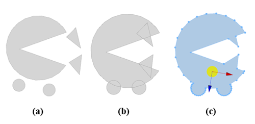
The Union Shapes tool performs a Boolean union of all selected shapes. For example, to combine the individual shapes (a), move them over each other (b). Select all shapes and click Shapes > Union Shapes. This results in a shape with one polygon (c).

Note:
- Combine Shapes is different because it would create a shape with five polygons in this example.
- If the selected shapes are not intersecting or coplanar, they are combined.
Subtract Shapes
The Subtract Shapes tool performs a Boolean subtraction of the lead-selection shape from all other selected shapes. For example, to subtract the triangle from the circle (a), move the triangle over the circle, select the circle, and press Shift and click the triangle (b). The triangle is highlighted in a different shade to mark it as the lead selection. Click Shapes > Subtract Shapes to subtract the triangle from the circle (c). Delete the triangle (d).

Offset Shapes
Select Offset Shapes in the Shapes menu. Select a shape or an individual face so an orange arrow appears (a). Drag the arrow to create an offset shape (b). Repeat by selecting a new face and dragging again (c). By deleting a selected face, a hole can be created in the offset shape (d).

To enter a offset distance, open the Tool Options window  by clicking Window > Tool Options in the CityEngine main menu.
 Offset Shapes Offset Shapes | |
| Distance (m) | The offset distance in meters. You can enter a value and press Enter to apply. |
Reverse Normals
This operation reverses the normals (i.e., the orientation) of all selected faces. This step is often necessary after importing shapes with reversed orientation.
Remove Holes
Removes all holes from the selected shapes.
Convert Models to Shapes
In order to manually edit CGA generated models, they have to be converted to shapes first, using this command.
Note:
After this conversion, changes in attributes and CGA rules do not affect the shapes anymore.