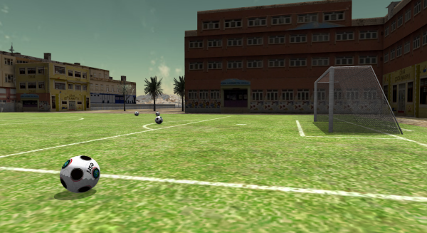
To access the tutorials in CityEngine, click Help > Download Tutorials and Examples.... After choosing a tutorial or example, the project is automatically downloaded and added to your workspace.
Tutorial Steps
Exploring the Desert City scene file
- Double click the Desert City scene file, which is located in the scene folder.
- Click Generate in the first dialog which opens.
This triggers the Model generation of all elements.
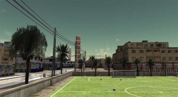
- Navigate through the scene and explore the buildings, streets and vegetation.
You’ll notice that only a fraction of all buildings are generated by default. This is obviously the case to save memory resources.
- Edit some rule parameters, such as Building_Height, Building_Usage, or the Level of Detail.
- Select some more building footprints or street shapes (left mouse botton click or draw a selection rectangle).
Note:
There is different behavior if you select ‘left-right’ or ‘right-left’ with a selection rectangle!
- Click the Generate button in the toolbar or press ctrl-g (apple-g on MacOS) to trigger the Model Generation of the newly selected shapes.
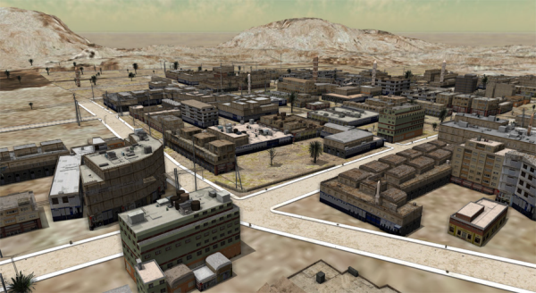
Recreating the full scene
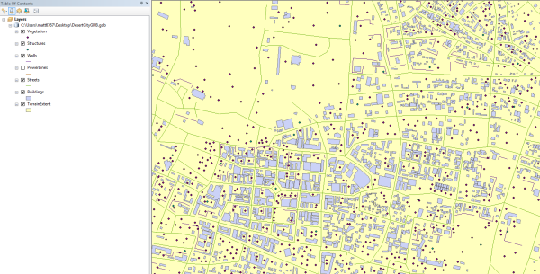
The complete ‘Desert City’ scene is composed of a GIS data and a rule set. The GIS data includes attributed footprint shapes, street center lines, vegetation markers, wall lines and electric power lines. All that data is contained in a so-called ‘GeoDataBase’ file, short ‘GDB’. Since there are different datatypes used (lines, polygons, points), each object type is stored in a different layer.
- Open the Desert_City_terrain_only scene file.
Import of GIS Data
- In the Navigator Window, locate the data folder. From within the data folder, drag-and-drop the DesertCityGDB.gdb directly into the 3d viewport. This triggers the GDB Import Dialog.
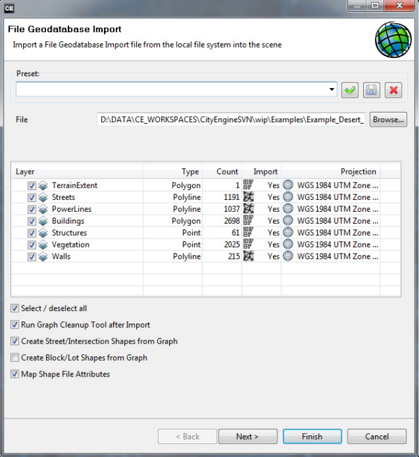
- Uncheck the TerrainExtent layer.
- Click Next and in the following settings, just activate the Merge Nodes option with a Merging Distance of 2, then click Finish.
Aligning of the imported GIS Data to the Terrain
In the Scene Editor, we see that all layers got created, but nothing is yet visible due to the fact that all elements come in at 0 elevation, thus we’ll need to project them to the correct heights and re-align the terrain accordingly:
- Deactivate the visibility of the Layers: PowerLines, Structures, Vegetation.
- Select all visible in the viewport with a large selection rectangle.
- Click Graph Menu > Align Graph To Terrain ...
- Project to the Terrain, with an Offset of 0.4 meters.
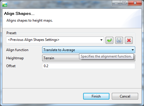
- Click Shapes Menu > Align Shapes To Terrain ...
- Translate to the Maximum of the Shape, with an Offset of 0.2 Meters
Note:
(Translating keeps the shapes horizontal and flat.)
- Click Layer Menu > Align Terrain To Shapes ...
- Align the Terrain +- 250 meters.
- Invert the visibility of all Layers, so the previously hidden ones are now visible and vice versa.
- For the upcoming alignments, we’re leaving the Terrain as it is currently.
- Project the Graphs (Walls and PowerLines) with an Offset of –0.5 meters.
- Translate the Shapes (Structure and Vegetation Markers) to the Maximum of the Shape, with an Offset of -0.5 Meters.
CGA Rule Assignment
Now, let’s assign the according CGA Rules to each specific object type. To do so, it is easiest to activate each Layer’s visibility one after the other to be able to easily select all shapes for the Rule assignment
Please note that there are multiple ways to assign Rules. Most common are:
- Drag-and-dropping the Rule from the Navigator directly onto selected shapes in the viewport.
- Use the Assign button in the Inspector Window.
- Right-clicking on a layer.
Due to the fact that the Marker shapes (Stuctures and Vegetation) are very small, it is tricky to assign the Rule via Drag-and-Drop. Thus, it is best just to right-click on those Layers and selecting all objects in the same Layer, then assigning the Rule via the Navigator.
| Streets | > Desert_City_Streets.cga |
| PowerLines | > Desert_City_Powerlines.cga |
| Walls | > Desert_City_Walls.cga |
| Buildings | > Desert_City_Buildings.cga |
| Structures | > Desert_City_Structures.cga |
| Vegetation | > Desert_City_Vegetation.cga |
Increasing texture resolution in the city center
CityEngine stores all textures (= raster images) for the 3d display in the video memory of the graphics card, thus there is a recommended maximum resolution for all texture files used in CityEngine, which is about 4000x4000 pixels, which may not be enough detailed for large areas. (See also Textures - raster files: concepts in CityEngine-ArcGIS).
To increase the quality of the Terrain texturing underneath the builidings at least locally, we’ll activate the dynamic Block Subdivision and use those new Lot shapes as a ground underneath the builidings. Onto that additional ground, we map a higher-resolution texture.
- First, hide all Layers except the Street Layer.
- Select some Blocks with a right-left rectangle selection. In the Inspector, go to the Blocks tab and change the shapeCreation parameter to true, then set the lotAreaMin and Max to 2’000 and 4’000.
- In each Block, select one shape, then select all shapes in the same group (right click context menu). Once you have the selection, assign the Rule called Desert_City_ParcelTexturing.cga.
- Click Generate.
Focus Intervention: New School
The GDB for this chapter is available in the data folder as ‘DesertCity_Intervention.gdb’. People not interested in the actual manual creation of that data may skip this chapter.
Let’s recreate a realworld focus intervention. At the following block near the city center, let’s plan a new school with soccer field in the following chosen city block.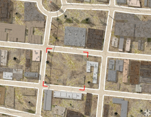
Our GIS application to edit the data is ArcMap, so let's open the dataset in ArcMap.
- Create a blank map in ArcMap and import the feature classes from the example dataset as layers DesertCityGDB.gdb.
- For the actual intervention, create a new GDB, name it e.g. MyIntervention.gdb. It is best that you directly locate the GDB in your project’s data folder on your harddrive.
- Create the following Feature Classes:
- Polygon Features: named Intervention_Buildings
Add the following attributes:
- Building_Height (of type float)
- Building_Usage (of type text)
- Polygon Features: named Intervention_Soccer_Field
Add no attributes:
- Point Features: named Intervention_Vegetation
Add the following attributes:
- Size (of type float)
- Line Features: named Intervention_Walls
Add the following attributes:
- width (must be lower case!) (of type float)
- Create the different features: Draw one or multiple school buildings, with realistic heights [meters] and set the Building_Usage attribute to school.
- Create some walls as polylines, set the width to 0.4 meters. The width value will be mapped directly in CityEngine.
- Create a rectangular Soccer Field.
- Distribute some Vegetation Points and set their Size attributes to realistic values between 2 and 15meters.
- Save the GDB.
- Unless you created the GDB in the project’s data folder, move or copy it there.
- Refresh the workspace in CityEngine: File > Refresh Workspace.
Importing the Intervention Data
As described in chapter 2, drag-and-drop the new GDB into the 3d viewport to trigger the import. Of course, you can choose either the GDB you have created yourself or the one shipping with the Example, DesertCity_Intervention.gdb.
- Align the Shapes and Graphs to the Terrain.
- Assign the rules. There’s also a rule for the Soccer field.
- In case the Soccer field is created in the wrong direction, set the attribute Orientation_Change to true.
