The Development Impact Analysis solution delivers a set of capabilities that help you create solar radiation maps, evaluate how proposed developments will cast shadows on existing buildings, and review the impact on viewsheds.
In this topic, you will learn how to use the solution by assuming the role of a user and performing the following workflows.
Shadow impact analysis
Planners can use Shadow Impact Analysis to evaluate the shadow impact of proposed or existing buildings on the surrounding community.
Two tasks are available to assess shadow impact:
- Check Shadows
- Analyze Shadows
Check shadows
You will start by assuming the role of a planner responsible for evaluating the shadow impact of proposed or existing buildings on the surrounding community. You are asked to use the Shadow Impact Analysis ArcGIS Pro project to review potential shadow impacts of proposed or existing buildings. Follow the Check Shadows task to do a quick visual shadow check.
- Download the ShadowImpactAnalysis Desktop Application Template and unzip.
- Open the ShadowImpactAnalysis.aprx in the unzipped folder.
- On the View tab, in the Windows group, click Catalog, and click Catalog Pane.
- In the Catalog pane, expand the Tasks folder, and double-click the Check Shadows task.
- Follow the steps in each task.
Note:
Only use the created sun point locations for display purposes. All shadow impact calculations are based on the attributes of the sun points features, not the display location. Use Observer Horizon Distance to set the distance to the observer.
Analyze shadows
Next, you will continue with the role of a planner responsible for evaluating the shadow impact of proposed or existing buildings on the surrounding community. Follow the Analyze Shadows task to evaluate shadow impact of features by calculating cumulative shadow duration and area for the time period of interest.
- Download the ShadowImpactAnalysis Desktop Application Template and unzip.
- Open ShadowImpactAnalysis.aprx in the unzipped folder.
- On the View tab, in the Windows group, click Catalog, and click Catalog Pane.
- In the Catalog pane, expand the Tasks folder, and double-click the Analyze Shadows task.
- Follow the steps in each task.
The Create Shadows step creates shadow panels on the observer features that will hold the shadow attributes:
- shadow_h—The number of hours each observer panel is in shadow
- shadow_hits—The number of time intervals (sun positions) each observer panel is in shadow
- num_suns—The number of suns
- start_date—The start date and time
- end_date—The end date and time
Note:
Check Shadows task only shows shadows as graphics in the scene, giving you a visual indication of where the shadows are going to be. The Analyze Shadows task allows you to evaluate shadow impact of features by calculating cumulative shadow duration and area for the time period of interest. This analysis takes longer to run than the Check Shadow task but calculates cumulative shadow duration and area as features with shadow attributes as opposed to only a visual display of the shadows.
Shadow hits are the number of suns that cannot been seen from the observer panel. Depending on the time interval, the shadow hits can be the same as the shadow hours (time interval is 1 hour), less than the shadow hours (time interval is more than 1h), or more than the shadow hours (time interval is less than 1h).
If your goal is to compare shadow impacts between different conditions, you must run this task multiple times, once per scenario in the comparison, such as existing versus proposed conditions. For example, the proposed scenario includes a model for a new development in the list of obstruction features along with existing buildings, whereas the existing conditions only include existing buildings in the obstruction features.
To create shadow panels for a specific time during the day (for example, 10 a.m.), open the Sun Positions attribute table and click a record that corresponds to the time interval of interest. This selection is honored by the Create Shadow step.
Solar radiation analysis
You will now assume the role of a planner responsible for calculating solar radiation maps for the wider community. You are asked to use the Solar Radiation Analysis ArcGIS Pro project to visualize solar radiation on the ground as well as on the roofs of buildings in a 3D scene and evaluate total solar radiation per selected roof area. Follow the defined tasks to calculate solar radiation rasters, visualize solar radiation on building roofs, summarize solar radiation for selected roof areas, and publish the results.
- Download the SolarRadiationAnalysis Desktop Application Template and unzip.
- Open the SolarRadiationAnalysis.aprx in the unzipped folder.
- On the View tab, in the Windows group, click Catalog, and click Catalog Pane.
- In the Catalog pane, expand the Tasks folder, and double-click the Solar Radiation Analysis task.
- Follow the steps in each task.
Note:
The atmospheric parameters used in this analysis are calibrated to historic solar radiation averages provided by the NASA Surface meteorology and Solar Energy global datasets.
These averages are provided at a one-degree resolution for the globe. While this resolution is adequate for most analyses, there may be some inaccuracy in areas with high variability in weather patterns over short distances. The accuracy of the solar radiation values is dependent on the quality of the input data.
Visibility analysis
Government agencies can use Visibility Analysis to assess visibility for the wider community. For example, planners, architects, and real estate appraisers can use Visibility Analysis to determine visibility of or from a proposed development from or of surrounding locations. Event planners can use the solution to calculate event visibility from specific locations or surrounding buildings.
Two tasks are available to assess visibility:
- Explore Visibility
- Analyze Visibility
Explore visibility
You will now assume the role of a planner responsible for conducting visibility assessments. You have been asked to use the Visibility Analysis ArcGIS Pro project to determine visibility of or from a proposed development from or of surrounding locations. Follow the Explore Visibility task to quickly explore visibility in your scene.
- Download the VisibilityAnalysis Desktop Application Template and unzip.
- Open the VisibilityAnalysis.aprx in the unzipped folder.
- On the View tab, in the Windows group, click Catalog, and click Catalog Pane.
- In the Catalog pane, expand the Tasks folder, and double-click the Explore Visibility task.
- Follow the steps in each task.
Note:
Typically, these tools are used to get an idea of visibility in your scene. The analytical results displayed by these tools are temporary and are not saved with the project, nor are they included in map packages. If you require analytical results as data including a measurement of how visible an object is, consider using the Analyze Visibility task.
Analyze visibility
Next, you will continue with the role of a planner responsible for conducting visibility assessments. You have been asked to use the Visibility Analysis ArcGIS Pro project to determine visibility of or from a proposed development from or of surrounding locations. Follow the Analyze Visibility task to perform a detailed visibility assessment.
Note:
This task calculates the perceived and actual visible area of the target as an attribute of the observer. Distance and angle are considered when calculating perceived visibility because targets that are further away and under an angle from the observer appear smaller.

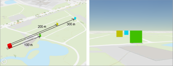
Objects that are further away from the observer appear smaller and are less visible compared to the objects that are closer to the observer.
Also, the angle of the targets in relation to the observer is considered because if a target is facing slightly away from the observer, it is less visible.

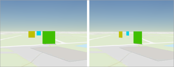
Targets facing away from the observer appear smaller.
- Download the VisibilityAnalysis Desktop Application Template and unzip.
- Open the VisibilityAnalysis.aprx in the unzipped folder.
- On the View tab, in the Windows group, click Catalog, and click Catalog Pane.
- In the Catalog pane, expand the Tasks folder, and double-click the Analyze Visibility task.
- Follow the steps in each task.
Note:
Analyze Visibility samples the observer and target features in 3D space and creates the following attributes on each observer panel describing the target visibility from the observer panel:
- Deviation—Average angle between the observer and target panels.
- ActualArea—The actual area of all targets visible from the observer.
- PerceivedArea—The perceived area of all targets from the observer, adjusted for distance and angle. The area of the closest target is used to proportionally calculate the target areas that are further away.
- PerceivedAreaPercentage—Percentage value of PerceivedArea. This attribute is typically used for symbolization.
- NumOfSightLines—Number of sight lines from the observer to all visible target panels.
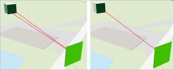
The average angle of the observer feature panel in relation to the target lines of sight is saved in the Deviation attribute. Currently, the observer deviation is not used in the visibility calculations, meaning all observer panels that have a deviation of less than 90 degrees are considered to have line of sight on the targets. Use Select By Attributes on the Deviation attribute to find the panels than have a smaller angle or window of visibility.

Visibility is shown on the observer in the upper left without taking into account deviation (left image) and with deviation less than 45 degrees (right image).