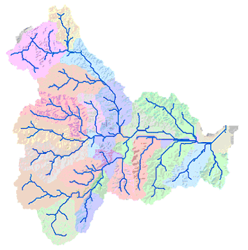
The hydrologic modeling tools provide methods for describing the physical components of a surface. The hydrologic tools allow you to identify sinks, determine flow direction, calculate flow accumulation, delineate watersheds, and create stream networks. The image below is of a resulting stream network derived from an elevation model:

Using an elevation raster or digital elevation model (DEM) as input, it is possible to automatically delineate a drainage system and quantify the characteristics of the system. The following graphics illustrate the steps involved in calculating a watershed and stream network from a DEM.
The DEM on which the hydrologic analysis will be performed.

Input DEM surface raster Using the DEM as input to the Flow Direction tool, the direction in which water would flow out of each cell is determined.

Flow direction is determined. With the Sink tool, any sinks in the original DEM are identified. A sink is usually an incorrect value lower than the values of its surroundings. The depressions shown in the graphic above (the scattered colored points) are problematic because any water that flows into them cannot flow out. To ensure proper drainage mapping, these depressions can be filled using the Fill tool.

Sinks are identified. Using the Watershed tool, the watersheds are delineated for specified locations. However, if you want to calculate only the stream network, this step can be ignored.

Watersheds are delineated. To create a stream network, use the Flow Accumulation tool to calculate the number of upslope cells flowing to a location. The output flow direction raster created in a previous step is used as input.

Flow accumulation output A threshold can be specified on the raster derived from the Flow Accumulation tool; the initial stage is defining the stream network system. This task can be accomplished with the Con tool and an expression that sets all cells in the input value that are above the threshold to a value of 1.
In this example, the expression would define all cells with more than 100 cells flowing into them as part of the stream network, and cells that have fewer than that threshold would be NoData..
To represent the order of each of the segments in a network, apply the Stream Order tool. The available methods for ordering are the Shreve and Strahler techniques.

Output from stream ordering Using the Flow Length tool, the length of the flow path, either upslope or downslope, from each cell within a given watershed can be determined. This is useful for calculating the travel time of water through a watershed.

Flow length output