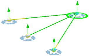
Interactive line of sight is used to determine if one or more targets are visible from a given observer's viewpoint in a 3D scene. It is calculated against the currently displayed content in the view, including the ground surface and symbolized features such as buildings and trees.
Both the line of sight observer and target locations can be interactively moved through the view. The analysis parameters, vertical offsets, and view distances can be used to model real-world objects such as a person's height and binocular range. A line of sight analysis can be based on a single observer with one or more targets created from a selected path or an existing line layer.
Note:
Each line of sight object consumes part of your analytical tool display budget. Once the display budget has been exceeded, you must remove one or more of the existing lines of sight before you can create another.
The analytical results displayed by these tools are temporary and are not saved with the project, nor are they included in map packages. However, their distance settings and geometry can be exported out as a line feature class for further use. If you require the displayed analytical results as data, consider using the geoprocessing tools for visibility instead.
Create an interactive line of sight
The interactive Line of Sight tool  is located in the Exploratory 3D Analysis gallery in the Workflows group on the Analysis tab. As you save templates with custom configurations, they are added to the gallery.
Interactive line of sight creation parameters
Interactive line of sight creation parameters are described in the following table:
| Option | Description |
|---|---|
Observer Vertical Offset | The vertical offset distance to use when creating the observer point for a new line of sight. For example, a value of 6 feet places the observer 6 feet above the clicked location in the view. |
Observer Minimum Distance | The minimum distance from the observer to analyze. Obstructions closer than the minimum distance do not participate in the analysis. |
Observer Maximum Distance | The maximum distance from the observer to analyze. Obstructions farther than the maximum distance do not participate in the analysis. |
Target Vertical Offset | The vertical offset distance applied to the clicked location when creating a target point. |
Note:
The observer and target control points honor the option to navigate below ground for the scene. Therefore, to move control points below the ground elevation surface, you must enable this capability. Select the elevation surface in the Contents pane, and on the Elevation Surface Layer tab in the Surface group, check the Navigate Underground option. This property applies a 2-meter offset from the ground to ensure the point remains above ground when the scene changes the ground surface level of detail.
Creation methods
There are four methods for creating an interactive line of sight:
| Method | Description |
|---|---|
Click in the view to place the observer position. Click again to place one or more targets. This is the default method. | |
Position the view to set the camera as the observer. Click in the view to place one or more targets. | |
Use a selected line to create a line of sight based on a number of targets or a segment length. Multiple lines are processed as a single route where possible. | |
Automatically generate lines of sight based on a line layer where feature attributes populate parameters such as minimum and maximum distances. Previously exported analysis objects can be revisited using this method. |
Update an interactive line of sight object
To update the analysis area for an existing line of sight, select the observer with the Line of Sight tool  and use the interactive handles to adjust the location. You can reposition the objects in the x- and y-planes or drag the green arrow to move in the z-plane. The updated values are dynamically displayed.

If you prefer to manually type values, you can update specific properties for a selected line of sight on the Properties tab in the Exploratory Analysis pane. In the pane, you browse each line of sight object in the scene to make iterative updates. Click All to modify all interactive line of sight objects at once.
Delete an interactive line of sight object
Select a line of sight object with the Line of Sight tool  and click Delete
  from the Properties tab to remove it. Alternatively, you can press the Delete key or right-click an object and click Delete
  . Delete all lines of sight at once by clicking Clear All
  in the Exploratory 3D Analysis gallery in the Workflows group on theAnalysis tab.


