The Simplify geometry tool simplifies the complexity of polylines or polygons by removing unnecessary vertices and maintaining only the most critical vertices.
Examples
The Simplify geometry tool can be used in scenarios such as the following:
- Your polyline data takes too long to process and your analysis does not require the high precision of the polyline vertices. Simplify the geometries to improve processing time.
- You have polygons with many vertices that require a large amount of storage space. Simplify the geometries to reduce the amount of storage space required.
Parameters
The following table outlines the parameters used in the Simplify geometry tool:
| Parameter | Description |
|---|---|
Input dataset | The dataset containing the geometry field that will be simplified. |
Geometry field | The polygon or polyline geometry field that will be simplified. |
Tolerance | The distance the output geometry can differ from the input geometry. |
Usage notes
Use the Tolerance parameter to specify the level of simplification. The larger the tolerance, the more coarse the resulting geometry. Smaller tolerances generate geometry that more accurately represents the input. The unit of the tolerance will be the same as that of the spatial reference of the input geometry field. For example, the units for a projected spatial reference with a unit of meters will accept values in meters, and a geographic coordinate system will accept values in degrees.
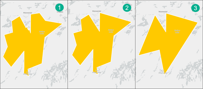
The diagram below is an example input geometry with complex edges (image 1). Image 2 has been simplified with a relatively small tolerance. The edges have been smoothed but the geometry still closely resembles the input geometry. Image 3 has been simplified with a high tolerance value, and the edge complexity has been significantly reduced.
The tool uses the Douglas-Peucker algorithm to simplify geometry. The Douglas-Peucker algorithm keeps critical vertices that depict the essential shape of a polyline (or the polylines that comprise a polygon) and removes all other vertices. The algorithm begins by connecting the endpoints of a polyline with a trend line. The distance of each vertex to the trend line is measured perpendicularly. Vertices closer to the line than the tolerance are eliminated. The polyline is then divided by the vertex farthest from the trend line, which creates two new trend lines. The remaining vertices are measured using these lines, and the process continues until all vertices within the tolerance are eliminated.
This algorithm is useful for data compression and for eliminating redundant details; however, the line that results may contain sharp angles and spikes that reduce the cartographic quality of the line. The best application of this algorithm is for relatively small amounts of data reduction or compression and when you don't need high cartographic quality.
Outputs
The tool output contains the same fields as the input dataset. The input geometry field will contain new, simplified values.
Limitations
The tool does not create a new geometry field. This means that the input geometry values will not be maintained. The input geometry field will be returned with new, simplified values.
Licensing requirements
The following licensing and configurations are required:
- Creator or GIS Professional user type
- Publisher, Facilitator, or Administrator role, or an equivalent custom role
To learn more about Data Pipelines requirements, see Requirements.